Hi MBK.
The only thing that I'd like to add to post # 13 has to do with L//R on the output. It's there to keep the amplifier from oscillating when driving a capacitive load, which could result from using long speaker cables or even the load itself. My amp works fine without it.
But if it does become an issue the best place to put it on my PCB version is between the amplifiers output terminal and your speaker output connector. It can also be installed under the board by cutting the trace that goes to the output terminal and putting it between the two.
Here are the Instructions from MikeB's site on how to build the output L//R listed as L1 and R7 in his schematic.
Around R7 is wounded a 0.6mm isolated (enamelled) copper wire forming the output coil. (~12 windings)
http://www.lf-pro.net/mbittner/Sym5_Webpage/symasym5_3.html
Al
Hi Al,
thanks again. Just for completeness sake, I take it that IGND and AGND are not separate, thus no R2.
thanks again. Just for completeness sake, I take it that IGND and AGND are not separate, thus no R2.
> Post #8
> Cascoded input stage..
If you are prepared to add a Zener, then I would suggest using MOSFETs for the cascode instead (e.g. ZVN3310A). Amongst others, it can take much higher voltage.
> Simpler..
You will find that most 2SK246s would not give you much more than -2V Vgs at 2mA, and the 2SK170s ideally would like to see at least 5V, preferrably >7V Vds. I suggest you try J111 instead. But then this does not solve your voltage problem (see above).
Patrick
Yes.Are the heatsinks from Conrad?
Isn´t possible to parallel the input to the rectifiers?(the AC side)For my version of Symasym you'll need two transformers
Otherwise I´ll have to buy another one.
 😀 😉
😀 😉Hi Ryssen,
No, I wouldn't recommend that. The amps will most likely develop a really nasty AC hum because they'll be sharing a common ground. Your better off buying a second transformer.
Al
No, I wouldn't recommend that. The amps will most likely develop a really nasty AC hum because they'll be sharing a common ground. Your better off buying a second transformer.
Al
You mean, you can't run several rectifiers off a single transformer's AC side? (just for the record. It's not aproblem for myself, I'll be using a central outboard rectifier beacause I already have it set up this way for existing amps).
If you had success doing that way then give it try. See what happens.
You'll then have to bypass D3 and connect your outboard rectified positive rail to the terminal nearest D3, and bypass D1 for the negative rail. Ground would be connected to the center terminal.
You'll then have to bypass D3 and connect your outboard rectified positive rail to the terminal nearest D3, and bypass D1 for the negative rail. Ground would be connected to the center terminal.
OK. What I am doing now is having a central rectifier and large smoothing caps, then going to a pair of chip amps with mid size (220uF) bypass close to the chip. No ground hum or such, but I was very careful with the grounding logic. Only problem is the long wire runs (several inches) due to point to point wiring, which I "conceptually" don't like, although there is no obvious problem. But, without oscilloscope, I have no means of testing whether some minor oscillations might have sneaked in.
Hi MBK,
The schematic below illustrates how to modify my PCB PS section in order to accept DC from an external PS.
All you need to do is connect a wire across R37 and R38, and use the 0.2 ohm resistors across D1 and D3 as illustrated in the schematic. Make sure you leave D2 and D4 open, if you mistakenly short or place a diode across them in your in for a major explosion. The positive voltage from your external PS is connected to the terminal nearest D3, and the negative voltage to the terminal nearest D1. The ground terminal is between the two.
This will provide a nice RC filter on board to reduce AC ripple even further.
BTW on your external PS what's the total filter capacitance per rail?
Here's the modified PS schematic.
Al
Make sure you leave D2 and D4 open, if you mistakenly short or place a diode across them in your in for a major explosion.
Attachments
Hmm,just thinking of tubeamps,where thy have MANY rectifies on the same winding,and it seems to work.?

Hi Ryseen,
What I'm saying is that if you connect a single transformer by fanning out both AC lines and center tap to two amplifiers, most likely that will cause both amplifiers to hum.
Now if you connect a singe transformer to a properly designed DC PS with rectifier and adequate AC filter caps, and then fanout each +/- DC voltage and ground to each amplifier that should work without hum.
Greg Ball's GB150S2 is a good example of a PS board specifically designed for two amplifiers using a single transformer. You can see in the picture the board has a DC output terminal for each amplifier on both sides of the board.
http://www.ska-audio.com/diy/006.html
Al
BTW I just completed a tube front end specifically designed for Symasym. It's has lower distortion levels than I thought it would have, but it does add some 2HD. Initial impressions are really promising. I still have about five different types of 6922s to go through.
Here's a pic.
Here's a pic.
Attachments
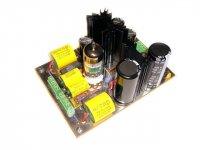
Thanks roender for the information. I agree it's not necessary, especially if 2HD can be increased by other means. But, with symasym's low distortion some may like this option. I've enjoyed so far playing with different tubes and evaluating how each sound. It's all in the spirit of DIY audio.
Best regards,
Al
Best regards,
Al
Hi Al,
thanks for the PS info. I now have transformers in separate housings with DC output, with either 10,000 uF or 22,000 uF. Trouble is they are 35 V rated and my DC with my line voltage has a tendency to overshoot the ca. 34-35V voltage I am supposed to get from 24V transformers. So while this has now worked for years, I'm feeling uncomfortable with it so I'll probably just use proper 50V caps on the PCB with the wiring you suggested, and w/o those borderline spec'd upstream smoothing caps.
thanks for the PS info. I now have transformers in separate housings with DC output, with either 10,000 uF or 22,000 uF. Trouble is they are 35 V rated and my DC with my line voltage has a tendency to overshoot the ca. 34-35V voltage I am supposed to get from 24V transformers. So while this has now worked for years, I'm feeling uncomfortable with it so I'll probably just use proper 50V caps on the PCB with the wiring you suggested, and w/o those borderline spec'd upstream smoothing caps.
I decided to go for 2 trafos in this explendid amplifier.🙂 2x28v I can find in 120VA,will they be enough?Higher VA is 2x30v but I prefer 2x28v.
Also 2x24v but thats a little low i think.So will 2x120VA be enough?
For 8 ohms that is.
Also 2x24v but thats a little low i think.So will 2x120VA be enough?
For 8 ohms that is.
Should R22 (pot) be 100 ohm?The original is 1K,just wondering.🙄
And I have found an error in the Bom,it says that BC546B can take 230c/15A.But any way I think that is Obvious.😉 🙂
And I have found an error in the Bom,it says that BC546B can take 230c/15A.But any way I think that is Obvious.😉 🙂
Hi Ryssen,
If you use my BOM 100 ohms for R22 is correct. I made a mistake on the BOM for BC546B Q7,Q8. Should be 65V/625mw.
Your 2x120VA 28V transformer is a little low, I'd recommend 160VA or higher. But into 8ohms playing music at comfortable levels it should be fine.
Regards,
Al
If you use my BOM 100 ohms for R22 is correct. I made a mistake on the BOM for BC546B Q7,Q8. Should be 65V/625mw.
Your 2x120VA 28V transformer is a little low, I'd recommend 160VA or higher. But into 8ohms playing music at comfortable levels it should be fine.
Regards,
Al
- Home
- Amplifiers
- Solid State
- Symasym 5.3 "AAK model" builder's thread