sorry one more time
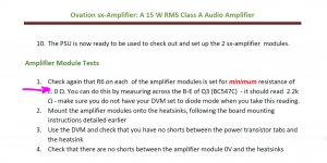
sorry Bonsai I have to clear something here, "I'm confused to be honest", okay so R6 need to be adjusted to 0Ω and from Q3 measure across B-E it should have 2.2KΩ if R6 is 0Ω but if that condition is like that then when turn on the first time is gonna be already on the 1.4A the setting that the circuit needs to be to operate in class A, is not better to have R6 on maximum resistance first before power up? or maybe set to 250Ω? I can be wrong
having R6 at maximum resistance @22 supply voltage I got from emitters R25 and R24 about 410mV that is a 1.2A to star
then R6 to slowly adjust till R24 and R25 have a reading of about 450mV giving the goal of 1.4A
but if R6 set to 0Ω does not cause any problems then put a 😀 and it will be answer and done deal and I will move on on the project 🙂
Attachments
Last edited:
There was a change made to the document to correct for this - might be the wrong version of it up on the website. The PCB was changed as well ( I’m going back 8 years).
For the circuit you show, you must set the potentiometer to MAXIMUM.
For the circuit you show, you must set the potentiometer to MAXIMUM.
R7 value on the PSU
I'm reviewing the BOM to be sent to Mouser and I have a problem for R7 in the PSU schematics.
Sometimes I see R7=5.6k, sometimes I see R7=22k.
What is the correct value?
Thanks
I'm reviewing the BOM to be sent to Mouser and I have a problem for R7 in the PSU schematics.
Sometimes I see R7=5.6k, sometimes I see R7=22k.
What is the correct value?
Thanks
I'm happy to see now that in the pdf documenting the project, in the BOM's, all those modifications has been taken into account.
Great!
And thanks again.
Great!
And thanks again.
ZN C and R or R and C?
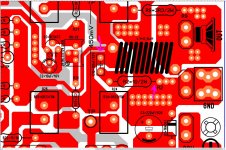
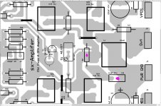
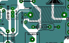
hi guys I have a question I was cloning the PCB and I know that Alex MM clone the one that Andrew made then me okay, the ZN I notice on Alex PDF that he place the C10 before the coil then resistor in series to GND but in the original layout by Andrew I think he did it differently resistor to coil then in series to C10 to GND is this really don't matter? the grey layout is the actual gerbers from the website the red one is the one I'm working now and the green one is from Alex's PDF I just want to be sure to get it right
hi guys I have a question I was cloning the PCB and I know that Alex MM clone the one that Andrew made then me okay, the ZN I notice on Alex PDF that he place the C10 before the coil then resistor in series to GND but in the original layout by Andrew I think he did it differently resistor to coil then in series to C10 to GND is this really don't matter? the grey layout is the actual gerbers from the website the red one is the one I'm working now and the green one is from Alex's PDF I just want to be sure to get it right
Attachments
The order is not important. What IS IMPORTANT is that you always fit a Zobel and the R and C are connected before the coil.
Alex MM's board is probably better than mine because he mounted the Zobel on the amplifier board and so kept the Zobel loop area much smaller around the OPS.
For those of you using my board (sold by Jim's Audio) make sure the connection to the Zobel which is on the PSU board is short and twisted tightly with the power supply cables.
These comments about the Zobel apply to all amplifiers BTW.
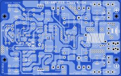
Thank you Bonsai for the quick replay here is the image of the PCB I like the design I just made a few changes to avoid the jumpers I still checking for bugs, question, the coil can be with a 12 or 14 gauge enamel wire? I saw pictures with really large gauge enamel wire
Attachments
Last edited:
about 16 AWG ok thank you
"The common standard for the diameter (gauge) of round drawn wire is the American Wire Gauge (AWG). As strands of wire are made, they are drawn through progressively smaller dies."
"The common standard for the diameter (gauge) of round drawn wire is the American Wire Gauge (AWG). As strands of wire are made, they are drawn through progressively smaller dies."
"...the decimal method of indicating wire diameters..has the advantage of being self explanatory, whereas arbitrary gage (sic) numbers are not...Gage numbers are gradually being discarded."
Machinery's Handbook p 471 1978
40 odd years later some still use this nonsense.
My micrometers don't measure in gauges. Why should we have to look up a table?
Brian
Machinery's Handbook p 471 1978
40 odd years later some still use this nonsense.
My micrometers don't measure in gauges. Why should we have to look up a table?
Brian
Some more clarifications, please
Hi Bonsai,
excuse me if I ask you some more questions. Let me hope that they will be useful also for other people. Due to the pandemic I proceed soo slowly!
Hi Bonsai,
excuse me if I ask you some more questions. Let me hope that they will be useful also for other people. Due to the pandemic I proceed soo slowly!
- You suggest a 500W power transformer, however in the Toroidy.pl site they suggest for such power an inrush current limiter. Do you agree? (it seems that you consider it unnecessary)
- You suggest to use BC550C and BC560C instead of BC547C and BC557C. However BC560C are hard to find (or the minimum qty is far too high).
However I was able to find on TME the BC547CBK-DIO, BC557CBK-DIO and BC546BBK-DIO, BC556BBK-DIO made by DIOTEC SEMICONDUCTOR.
Let me guess that I can use those. - R4=100kOhm is missing from the BOM. In the simulation it's absence is not substantial, apart a slight increase of output power
soft star like this ? (example) your outlet is 120V AC or 220V AC? but why 500VA? I think with 400VA will be just enough in my opinion I think
Attachments
Last edited:
Teodoro,
1. I have not used an in-rush limiter on my DIY amps using a 500W transformer a d have had no problems. Unfortunately I don’t have a DIY circuit (my commercial amps protection are all MCU based).
2. The Diotec parts should be ok
3. R4 - yes the transistor still has bias through the other resistors so it’s not critical. It was a left over because I initially was going to AC couple the input. The amp will function without it.
Last edited:
- Home
- Amplifiers
- Solid State
- SX-Amp and NX-Amp