Another silly recommendation, if I was You, I will try to short input on both RCA socket (inside amp) and connect PC via cables you are using and see what happens. If amplifier will not have any oscillation, then you have correct working amplifier, but you have signal injector via your source (PC).
I also had similar problems with another amplifier with wide bandwith and for sure I have to connect both input grounds from input sockets to exclude oscillation.
On your picture where input signal wire passes near the output wires of the amp I can't see how far they are (another part of the path, beside the filter cap and the amp module, you showed on another picture part from socket to the filter cap). Consider that path and put away input wires from the output wires.
Check how long are your power supply GND wires for both channels, I suggest that they are of same thickness and same lenght.
Thanks for your input pibul. Not a silly recommendation/suggestion at all, I appreciate you thinking along a lot! However, I isolated the problem to the amplifier itself.
I can induce the phenomenon by just gently touching the inputs while having a dummy load connected. Basically I inject 50Hz by acting as an antenna. However, at the output I see a sine wave, with no visible harmonics, of more than 200KHz (frequency varies depending on how hard you touch / changing resistance). It happens only when the dummy load is attached (so the amp can dump its energy). It happens with both channels independently. I removed the signal cables to make sure I was not picking up noise (the cables are twisted, but not shielded yet, I will replace that later). However, even with no signal cables attached, and just touching the input on the PCB itself / inducing hum, immediately causes the same effect. It would be logical if the amplified hum signal is 50Hz, but it is somehow transformed. That transformed hum signal causes the Zobel to heat up. The strange thing is, when I apply a sine wave with a signal generator, there is a perfect sinewave at the output of the right frequency. And that till +2MHz. My scope has a limited FFT function, but no harmonics can be detected. Also I do not see any ringing when applying a square wave of 1KHz.
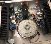
Shorting the input to GND immediately resolves the issue. It is in that sense not a spontaneous oscillation but occurs thus far only when I induce 50Hz hum by 1) connecting a cable that is not properly shielded (hence the issues I described earlier and for which I blamed the PC) 2) touching the input with my fingers. The harder I press the lower the frequency of the oscillation. Input and output wires are for the left channel indeed close. To check if this induced somehow a loop I disconnected all input wires and touched the PCB directly at the signal input. That results into the same effect. Also it is for both channels exactely the same. When it is wire induced I would think there should be at least some difference between both channels. Making me believe that it is mere in the PCBs than wiring itself. All wires are twisted and kept as short as possible (Bonsai made once a nice .pdf about ground loops, I tried to follow this the best I could and on basis of best practises). I attached a picture that shows the wiring a bit better. For example I am not really happy with the RCA's in this position; for the left channel the signal wire is much longer. But the cabinet came already with pre-drilled holwes. Based on what I have seen thusfar I think somehow it is related with RF decoupling. Apparently we have to find a way to reduce the Q-factor of this circuit a bit. But I am not sure where it is best to try (for me the first time I got an amp reacting this vigorous to hum 😀).
I can induce the phenomenon by just gently touching the inputs while having a dummy load connected. Basically I inject 50Hz by acting as an antenna. However, at the output I see a sine wave, with no visible harmonics, of more than 200KHz (frequency varies depending on how hard you touch / changing resistance). It happens only when the dummy load is attached (so the amp can dump its energy). It happens with both channels independently. I removed the signal cables to make sure I was not picking up noise (the cables are twisted, but not shielded yet, I will replace that later). However, even with no signal cables attached, and just touching the input on the PCB itself / inducing hum, immediately causes the same effect. It would be logical if the amplified hum signal is 50Hz, but it is somehow transformed. That transformed hum signal causes the Zobel to heat up. The strange thing is, when I apply a sine wave with a signal generator, there is a perfect sinewave at the output of the right frequency. And that till +2MHz. My scope has a limited FFT function, but no harmonics can be detected. Also I do not see any ringing when applying a square wave of 1KHz.
Shorting the input to GND immediately resolves the issue. It is in that sense not a spontaneous oscillation but occurs thus far only when I induce 50Hz hum by 1) connecting a cable that is not properly shielded (hence the issues I described earlier and for which I blamed the PC) 2) touching the input with my fingers. The harder I press the lower the frequency of the oscillation. Input and output wires are for the left channel indeed close. To check if this induced somehow a loop I disconnected all input wires and touched the PCB directly at the signal input. That results into the same effect. Also it is for both channels exactely the same. When it is wire induced I would think there should be at least some difference between both channels. Making me believe that it is mere in the PCBs than wiring itself. All wires are twisted and kept as short as possible (Bonsai made once a nice .pdf about ground loops, I tried to follow this the best I could and on basis of best practises). I attached a picture that shows the wiring a bit better. For example I am not really happy with the RCA's in this position; for the left channel the signal wire is much longer. But the cabinet came already with pre-drilled holwes. Based on what I have seen thusfar I think somehow it is related with RF decoupling. Apparently we have to find a way to reduce the Q-factor of this circuit a bit. But I am not sure where it is best to try (for me the first time I got an amp reacting this vigorous to hum 😀).
Attachments
Last edited:
Michael, have you made the mods per the latest kx build doc here
http://hifisonix.com/wordpress/wp-content/uploads/2021/01/kx-Amplifier-Dec-2020.pdf
See s.ides 4 and 5.
It looks like you have a loop stability problem, rather than parasitic instability which was the case with some of the earlier builds
As a start (after the above) Please check (measure) very carefully the following component values
C2, C3, C10 and R42
These are the main compensation components
OK,
I see another possible inerference, your input on both channels are close to the toroidal transformer. Try to put some shield (same material as your mounting panel for transformer and PS boar, it should be ferromagnetic) between transformer and both channels. It will screen transformer magnetic emissions to the input wires of the amplifiers. Aluminium is not best material for doing so.
Also, if you are using anodised aluminium, scratch the pad to bare metal to get better contact. Anodised aluminium tend to raise some potential over time (due to static charge) and from time to time you will have charging of the some parts of chassis. That means you don't have correct bonding between parts of your chassis.
Regards
I Gael, your build looks ok. We should focus on finding the source of the oscillation which looks to me like a loop stability problem per my earlier post. Note that if you had some really bad VAS transistors rather than those specified, you could also have this problem.
What happens if you connect a generator with a c. 50-100 Hz input and then slowly increase it? Does it break into oscillation at some specific input level?
What happens if you connect a generator with a c. 50-100 Hz input and then slowly increase it? Does it break into oscillation at some specific input level?
Last edited:
Please completely ignore my posts 2503 and 2505 above. I am mixing things up with the kx-Amp.
Apologies. I will come back to you in an hour with nx-Amp related feedback
(I’m getting old and losing it 😉. )
Apologies. I will come back to you in an hour with nx-Amp related feedback
(I’m getting old and losing it 😉. )
Thanks again Bonsai! I was not even aware that there is also a KX 🙂 Cool! I checked the document. I was not able to measure / reproduce a similar oscillation in the MHz range as seen in the KX.
I tried however the suggestions. I see that it was proposed for the KX to lower R4 and R5 to 1K. For the NX these resistors are R32 and R33. In the NX these already have a value of 1K. The voltage drop is about 1080mV, which seems to be nicely in range. I added 100nF capacitors parallel to the 1000uF capacitors (I did not have 1uF available, but I think 100nF should be also sufficient for decoupling). Unfortunatelly this had no effect. I checked C2 (220uF), C3 (10uF SMD), C10 (100nF) and R42 (0 ohm, SMD). The components measure OK and are fitted correctly.
I tried to reproduce the issue via the signal generator by turning slowly from 0.1Hz to 150Hz. I also tried to sweep from 0.1Hz to 100kHz. Unfortunatelly I was not able to reproduce the issue, although there is some movement at frequencies below 10Hz (offset seems to be affected). One thing is kind of funny, when the amps ground is connected to any device, I can not reproduce the issue. Only when no ground / no device is attached at the input, the problem appears.
As VAS I use KSC3503DS-ND and KSA1381ESTU-ND (from ON Semicon and ordered at DigiKey, for sure original), which I did not match by the way. Even though offset can be nulled out quite easily. A little bit of drift occurs, but in the order of max 10mV.
@Update Bonsai: haha, it happens ;-). But I do think you are completely right about the loop stability. There is no rush, thanks a lot for helping 😀!
Last edited:
Please ignore my previous posts - there's additional stuff in the kx that make it a very different amp.
On the nx-Amp, there is only one compensation component and that is C7 at 68pF.
Make sure this is the correct value - if it is accidently 6.8pF then you would have problems.
I don't know what type of cap you have used but for example on a silver mica cap it will probably be marked 680 for 6.8pF, for 68 pF 681 and for 680pF 682 - so you will need to check this carefully.
If the compensation cap is a XR5 or XR7 ceramic you would also get problems because the voltage coefficient is very high, so the capacitance will change dramatically (3 to 4 times) over the voltage swing and this could trigger oscillations. You should use a good quality film or NPO/COG ceramic or a silver mica type.
Note also that if Q7 and Q6 were not the correct parts, but say remarked MJE340/350 fakes, you would also get serious problems. If they are from Digikey, then it should be good.
Measure across D4 and D3 - you should have 10V +- say 40 mV
Measure across R37 and R36 - should be 150mV +-10mV
Across R29 and R28 should be 145mV +- 10mV
Across R33 and R32 1.1 to 1.2 V
Across R31 and R30 375mV +- 25mV
The nx-Amp is very stable normally and there have been no builder problems (121 board sets sold by Jim's Audio since 2012 - most of them built based on feedback from builders).
Can you check R43 - should be 15 Ohms - if it is blown (I've done this on testing on other amps) you could also have problems.
Michael, just relooking at your boards. What kind of 68pF capacitor are you using (Blue one)?
Hi Bonsai! I conducted some measurements:
1) Those blue capacitors are Philips KP polypropylene film and foil capacitors. I attached the datasheet and checked the value. It is 68pF.
2) Measure across D4 and D3 - you should have 10V +- say 40 mV
Measured left Ch D4 = 10.0 V
Measured left Ch D3 = 10.0 V
Right Ch D4 = 10.1V
Right Ch D3 = 10.1V
3) Measure across R37 and R36 - should be 150mV +-10mV
Measured left Ch R36 = 142 mV
Measured left Ch R37 = 142 mV
Measured right Ch R36 = 140 mV
Measured right Ch R37 = 141 mV
4) Across R29 and R28 should be 145mV +- 10mV|
Measured left Ch R28 = 130 mV
Measured left Ch R29 = 124 mV
Measured right Ch R28 = 140 mV
Measured right Ch R29 = 142 mV
5) Across R33 and R32 1.1 to 1.2 V
Measured left Ch R32 = 915 mV
Measured left Ch R33 = 910 mV
Measured right Ch R32 = 940 mV
Measured right Ch R33 = 930 mV
6) Across R31 and R30 375mV +- 25mV
Measured left Ch R30 = 225 mV
Measured left Ch R31 = 241 mV
Measured right Ch R30 = 278 mV
Measured right Ch R31 = 306 mV
R43 is for both channels OK and 15 ohm.
Not very big deviations from what is expected. R33, R32, R31 and R30 seem to be a bit off. R31 and R30 resistors are spot on 15 ohm and from Dale (actually the most expensive ones used in the amp 😛). R33 and R32 are 0.998K and cheaper Philips metal film resistors. Still spot on. What do you think Bonsai?
Attachments
Last edited:
Ok. Nice cap! Wouldn’t expect anything less from Philips (worked there for 10 yrs 😉 )
Voltages are all ok.
Is your Zobel connected? Can you show a picture of the amp output with a square wave input at about 2V pk ~pk?
Voltages are all ok.
Is your Zobel connected? Can you show a picture of the amp output with a square wave input at about 2V pk ~pk?
Last edited:
That is really cool! I bet it was a pleasure to work there :-D! Truly like Philips components. Somehow sad that many of Philips', sometimes very advanced products, were put too soon or not properly in the market. They are now mainly focussed onto the medical market and are about to sell their last consumer products branch (toasters, mixers etc.). The company shrunk but many former Philips devisions spun out and became quite large, world class companies like NXP and ASML. Philips even had a stake in TSMC. If they just made some different choices... fascinating and however still an innovative company. A really nice book is written about their labs (Natlab by Paul van Gerven). Unfortunatelly it has not been translated in English yet.
Thanks for checking Bonsai! Currently I disconnected the Zobel resistors because the oscillation would fry the Zobel within a minute. However, the effect is not altered by the Zobel; when connected the same happens, but with a bit more heat / smoke ;-). Are there be other things I could check, or could I maybe experiment a bit with C7?
Thanks for checking Bonsai! Currently I disconnected the Zobel resistors because the oscillation would fry the Zobel within a minute. However, the effect is not altered by the Zobel; when connected the same happens, but with a bit more heat / smoke ;-). Are there be other things I could check, or could I maybe experiment a bit with C7?
I was with NXP for 10 yrs also after the first 10 at Philips.
Could you replace C7? I’m just wondering if it’s faulty or if they are quite old.
The nx-amp is normally very stable with lots of gain and phase margin - this is the first issue like this that I had on this amp.
Could you replace C7? I’m just wondering if it’s faulty or if they are quite old.
The nx-amp is normally very stable with lots of gain and phase margin - this is the first issue like this that I had on this amp.
Cool! I guess there was quite nice equipment to work with and work on 🙂.
I just replaced C7. I did not have any fancy capacitors around, but used a normal ceramic one (NPO) of 68pF. Unfortunately it did not change much. Although I now got an extra effect; the speaker protection kicked in after 2 seconds of inducing hum. The Philips ones are NOS, I think they are at least a few decades old but they are really relieable.
I just replaced C7. I did not have any fancy capacitors around, but used a normal ceramic one (NPO) of 68pF. Unfortunately it did not change much. Although I now got an extra effect; the speaker protection kicked in after 2 seconds of inducing hum. The Philips ones are NOS, I think they are at least a few decades old but they are really relieable.


The nx-Amp output needs to be at 2.5 V pk -pk. So the generator output must be about 0.1V. We are looking for small signal stability
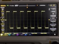
0.8mV on the input and 0.5V on the O/P - seems the gain is very high. Should a gain of 37x so for 2V pk~pk about 50mV
If you measure across the feedback resistors (R12-R16 in parallel) you should get 540 Ohms and R11 must measure 15 Ohms. Measure also from the junction of R29 and R28 to 0V - should also be 15 Ohms.
If you measure across the feedback resistors (R12-R16 in parallel) you should get 540 Ohms and R11 must measure 15 Ohms. Measure also from the junction of R29 and R28 to 0V - should also be 15 Ohms.
Last edited:
- Home
- Amplifiers
- Solid State
- SX-Amp and NX-Amp