Arif,
You will have to set it to about 50 mV with those heat sinks, but the adjustment range will not allow you to go that low. Suggest you mount the amplifier on the final hestsinkd, then you can adjust it.
You can set the output range between about 800mA total to about 1.4A total.
If you want it it lower than this, it will require resistor value changes.
Arif,
You will have to set it to about 50 mV with those heat sinks, but the adjustment range will not allow you to go that low. Suggest you mount the amplifier on the final hestsinkd, then you can adjust it.
You can set the output range between about 800mA total to about 1.4A total.
If you want it it lower than this, it will require resistor value changes.
If i remember well you told me that using a swicth is possible to choose two bias setting, one high and the other low.
That is correct Thimios. But Arif must first fix his heat sinks otherwise he will damage his amp.
That is correct Thimios. But Arif must first fix his heat sinks otherwise he will damage his amp.
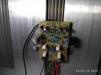
My second channel.. measured 187 mV at 0.33 r 5 w.. using mur 3060 diodes n need to get good quality trafo.. and bigger heatsinks..
For this moment it is ok.. I like the sound..
TKS Mr. Russell..
Attachments
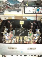
Don't have speaker protect. Is it necessary? I'll wait for Bonsai to answer that.
It is only 15w amp.
BTW: Think it looks kind of cool with the red glare in the cabinet.
And the speakers of course.
Onken cabinets, Hemp acoustics co15v drivers. (15" coaxial)


Why did you take the dust cap out from your Beymas?
All the best!

Hi all,
I'm finishing my dual mono SX build here but I'm having some difficulties. I have tested it according to the latest documentation. The first problem was that the quiescent current minimum value is around 1.29A, not ~300 - 400mA as in the documentation. Anyway, I adjusted it to 1.4A and it stays there after one hour (within 10mA).
The second problem is that there is absolutely zero volt dc offset at the output. That can't be right. Adjusting the DC offset trimmer does nothing. Once I turn the power off, then the DC offset jumps to ~50mV and drops down in a few seconds. I am thinking that probably I don't have any output at all for some reason. I'll test that later.
I have rechecked all the resistor values and I have checked the voltages on the board according to the Fig.5 in the documentation. All voltages are really close but across R32 and R33 I get ~1.2V and it should be 1.5V.
J2 is linked but I have R4 still fitted (but that shouldn't matter?)
Can anyone help debugging? Thanks in advance!
BTW, My amp boards are v2.0
An externally hosted image should be here but it was not working when we last tested it.
Last edited:
Actually, for DC offset measurement I had a bad test lead. Now I can adjust the offset. But there is still a problem... it drifts quite a lot. I can get it quite steady when playing some input signal with speaker connected... Yes, I finally got it running but for now I only tested it through laptop output.
Also, there is quite much noise in the signal. Could the noise and the DC offset problem be due to some bad transistor or other component?
I'll try to move the wires and turn the transformers a bit and see if that helps.
Also, there is quite much noise in the signal. Could the noise and the DC offset problem be due to some bad transistor or other component?
I'll try to move the wires and turn the transformers a bit and see if that helps.
Last edited:
Hello Piisami,
If you short the input and monitor the offset on the mV scale, it will drift around a bit by a few mV. The sx-Amp does not use a servo, so anything within a +-5 mV band once the amp is warmed up is good and quite ok. The drift within this band is mostly attributable to changing thermal gradients across the input diamond buffer transistors caused by airflow around the front end transistors. If you place a matchbox lid over these transistors, the effect will be reduced as it will be also when you put the amp modules into a case.
Re the noise, the sx-amp should be completely silent if wired up correctly ie no hum.
Please see below especially slides 54 to 72 for some guidelines
http://hifisonix.com/wordpress/wp-content/uploads/2019/02/Ground-Loops.pdf
Last edited:
Thanks Bonsai,
I must admit I feel myself stupid now.. I had forgotten to connect the transformer center tap to the PSU board 0V =). So that makes the psu ground floating, right? And this might be my main noise source. The noise is both, humming and hissing. Well, I have to put my ear quite close to the speaker to actually hear it. I'll fix this up next and let you know..
In your excellent "How to Wire-up an Audio Amplifier" write-up you mention that there should be an ~1nF - 2nF capacitor between the input socket ground and chassis and both channel input socket grounds should be connected together. I have not done that, should I?
BTW, I got the DC offset issues solved.
If you have your left and right input sockets next to each other and signal grounds are connected together ( but NOT to the chassis), you can use a single 1-2 nF cap from the signal ground to the chassis. This cap must be right at the input connectors. Keep the leads short.
This provides good RFI immunity.
This provides good RFI immunity.
I moved the input sockets really close together and connected the socket grounds together with copper wire and added a ceramic disc capacitor (actually 2x470pF since I didn't have 1-2 nF on hand) from this wire to the chassis right on top of the input sockets.
I also moved the wire routings from sockets to the amplifier boards, tried different routings. They go together to one amplifier and the other one continues to the other side by going first to the right front corner then to the left front corner and to the second amplifier board.
The input wire is silver plated ofc copper twisted pair with kapton insulation, silver plated copper braiding and again kapton insulated. Now, the positive signal in one wire in the twisted pair and signal return on the other. The braiding is connected on both ends to the signal ground.
Doing all that made the hissing disappear, but the hum is still there. The hum can be heard in all channels in my LX521 speakers. Hum is similar in all conditions, inputs shorted, inputs disconnected, inputs connected. I can hear the toroids humming mechanically, this mechanic hum is similar to what can be heard through the speakers. This made me think that i might have dc in the mains since my NAD amplifier toroid is also humming mechanically (but not through the speakers). Could this mechanic hum somehow transform to hum that can be heard through the speakers? Somehow I can't capture the hum with my digital scope.. well, it shows 10mV noise but almost no different that the base noise in the scope.
I also tried to rotate the toroids, but no effect.
The toroid primaries and secondaries are tightly twisted but not shielded. Toroids are 2x 250VA Toroidy audio grade (magnetic screening and copper tape between windings) brand new.
Hi Bonsai,
can you please help me?
1. Is it possible to have a “text” versions of the BOM: what you have published in the PDF is an image and it would take some time to get from it the Mouser order
2. I was able to simulate the amplifier circuit (see below); unfortunately the PSU image is so blurred that I’m unable to translate it into LTSpice. Is it possible to have a better version?
3. Does the PSU offered on eBay comprise the short-circuit and (DC) speaker protection? What about the "ripple eater"?
many thanks
An externally hosted image should be here but it was not working when we last tested it.
No answer ...
I needed to understand if the project is dead or alive.
I needed to understand if I can get any support if, after having bought the PCB's, I encounter a problem.
No answer ...
I needed to understand if the project is dead or alive.
I needed to understand if I can get any support if, after having bought the PCB's, I encounter a problem.
No answer ...
I'm here Teodorom - I did not see your post - looks like it must have gotten pushed off the front page of the thread.
The above is the nx-Amplifier schematic. The PSU incorporates protection features and I will shortly post up the schematic for the PSU.
rgds
Andrew
The above is the nx-Amplifier schematic. The PSU incorporates protection features and I will shortly post up the schematic for the PSU.
rgds
Andrew
Here is the NX Amplifier schematic
NB if using the ground lifter, no not fit R25.
NB if using the ground lifter, no not fit R25.
Attachments
Last edited:
- Home
- Amplifiers
- Solid State
- SX-Amp and NX-Amp