Thanks, but ... the BOM in the PDF had the Mouser P/N.
A lot appreciated, since Mouser is my preferred distributor.
Is it possible to have it?
Thanks
An externally hosted image should be here but it was not working when we last tested it.
A lot appreciated, since Mouser is my preferred distributor.
Is it possible to have it?
Thanks
Thanks Bill - I will have to check it first - there were a few tweaks along the way but nothing major. I’ll get back to Teodoro this evening.
Again, thanks for this
Again, thanks for this
Last edited:
Thanks, it's a big leap forward!
I had already started from what I could find in the PDF and I realized that some components are no more available.
I shall post an updated version ASAP.
Thanks again.
I had already started from what I could find in the PDF and I realized that some components are no more available.
I shall post an updated version ASAP.
Thanks again.
Here is a copy of Bill_P's file. I have checked the critical components on the PSU board and on the amp modules and (see the blue blocks on the RHS in the BOM's).
I cannot find a source for the fuse clips. These have offset pins. The manufacturer still lists them but I cannot find them at RS or Mouser - might be you need to look at DK. I put a link in the BOM to the data sheet.
BC547 and 557 are no longer available from Mouser but you can get the Taiwan Semiconductor BC550/560 series from RS but just make sure you use the same gain grade for all the input diamond buffer transistors.
VERY IMPORTANT NOTE: R36, R37 these are now 150 Ohms (NOT 15); R28, R29 are 120 Ohms (NOT 15)
Q7 and Q6 - it is not possible to easily get matched gain grades on these devices. My nx-Amp was built with the mispatched gain grades and it works very well so I would not worry about this.
Attachments
Last edited:
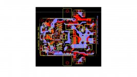
Does anyone know the exact dimensions of the double-sided pcb for the SX-amplifier ?
(I mean the PCBs sold by JIMS Audio)
(I mean the PCBs sold by JIMS Audio)
"... KX Amplifier - Quick OverviewDoes anyone know the exact dimensions of the double-sided pcb for the SX-amplifier ?
(I mean the PCBs sold by JIMS Audio)
Uses same PCB mounting footprint holes as the SX and NX amplifier, but the PCB is slightly longer (3cm) and slightly wider (2cm). ..."
I can provide you with measurements of my KX board in a moment, maybe that will help somewhat.
My KX amp PCB measures:
Width: 72 mm (the main part: input circuits); 97mm (the wide part, with extruding side wings (Vcc+, Vcc- and connectors); 68mm (the bit far on the right, with output coil and second pair of transistors);
Length: Total: 112mm (including the Speaker out connector extrusion); 107mm (not counting that output connector extruding part).
Detailed photo of my KX boards, as measured above, here:
Hifisonix kx Low Dist ,Wide BW 25 W Class A, 50W classAB CFA Amp PCB set stereo! | eBay
Does anyone know the exact dimensions of the double-sided pcb for the SX-amplifier ?
(I mean the PCBs sold by JIMS Audio)
I will have to measure it tomorrow - they are slightly smaller than the kx-Amp boards.
I will have to measure it tomorrow - they are slightly smaller than the kx-Amp boards.
Thank you. I'll wait for your response!
regards
George
Does anyone know the exact dimensions of the double-sided pcb for the SX-amplifier ?
(I mean the PCBs sold by JIMS Audio)
the Jim's Audio sx-Amp PCB's measure 100 mm x 97 mm
Thanks !
I believe these are the maximum dimensions.
Is that correct ?
No. The dimensions above are for the PCB only.
If you include the distance that the power transistors stick out from under the PCB then the worst case dimensions are 100 x 110 (includes 'side wings')
I just added the power transistor outlines below to show what I mean.
Attachments
Last edited:
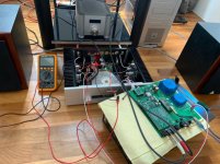
Dear all,
I was planning to start once again with finishing the SX Ovation amplifier in a chassis.
The soldering was finished a while ago but I had to take courage to start the set-up of the PSU and the tuning of the amplifier.
I had already started reading this section a few times but I couldn't figure it out and unfortunately I still don't do that, so I ask for advice again
So I started to check and test the PSU with a transformer. Everything seems to work and I have 21.3 V at the output. So far it seems good. But now I want to continue but I don't quite understand what to do with the fine-tuning for the amplifiers.
I now get no further than setting the R6 to +/- 0 ohm.
Amplifier Module tests: some questions
Point 4: Do I have to place a temporary 1A fuse(s) on the V-/V+ or will it be permanently in the circuit?
Number 7: Then set the Multimeter on 2A . I measure with the black / red pin to between the V + fuses from the UPS and the amplifier?
With 300-400mA as result and then set R6 on 1.4A.
Number 12: I don't understand anymore because again a 1A fuse is placed here.
(or is this part for tuning the second amplifier?)
Point 15: I have printed the circuit diagram and see the different values that are measured in red.
But how do I measure this with the Multimeter?
Simply left / right of the indicated resistor (s) with both pins of the Multimeter.
Or in another way?
For example, the + 150mV to be measured between Q9 and Q11, I certainly do not understand how to measure.
And what about the mentioned in Testing and set-up start text: 4x 5A 5x20 fuses?
These are already placed into the both amplifiers?
I have too little experience in this and I am afraid to make a short circuit with a measurement attempt with the Multimeter
Dear people, I hope you can help me through this last tricky part because the rest of the finishing is not so difficult and great fun to do.
With kind regards,
Frits
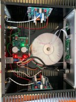
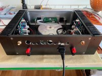
Humble sharing of nx-amp
Thank you so much for a wonderful designed amplifier. It’s dead quiet, solid and most importantly sounds great. Sharing some photos of my poor workmanship to encourage fellow hobbyist who is still contemplating if they should build it.
Regards,
Askae
Thank you so much for a wonderful designed amplifier. It’s dead quiet, solid and most importantly sounds great. Sharing some photos of my poor workmanship to encourage fellow hobbyist who is still contemplating if they should build it.
Regards,
Askae
Attachments
Hi Bonsai,
Sorry for the delay but my computer crashed so I had to buy and rebuild another one.
I'm checking the availability of the componens of the amplifier and I have some problem:
Many thanks
Sorry for the delay but my computer crashed so I had to buy and rebuild another one.
I'm checking the availability of the componens of the amplifier and I have some problem:
- 534-835, 534-836, 534-837 are not "TAB Connectors": let me guess that the P/N is still 534-834
- 771-BC847CT115 is no longer available, I was able to find 771-BC847CW-T/R that seems electrically equivalent, but has a different package: SOT-323-3 instead of SOT-416-3
- 652-3296W-1-102LF (10k Multiturn Trimmer) is not found on Mouser
- A100452CD-ND is not found on Mouser
Many thanks
BOM errata(?)
Dear Bonsai,
Thanks for sharing and thanks for all the stuff you published.
Can you please clarify some points and/or confirm that I'm not mistaking here.
On the BOM, I guess these are typos, but maybe it can help:
- item 5, qty is 1, I guess it should be 3
- the fuse you are not finding anymore, shouldn't it be 504-HTC-210M instead of 501-HTC-201M?
- R36,R37 are still referenced as 15 instead of 150 Ohms although you add the important note?
- R28,R29 are still referenced as 15 instead of 120 Ohms
For R36,R37,R28,R29, are these changes related to the use of BC550/560 instead of BC547/557 (sorry I'm totally noob) or is this something to fix whatever we use to build the NX?
I'm joining the BOM with all these "fixes" in red in the tab called "nx-amp BOM (errata)". Can you please confirm it's ok?
Thanks,
Raph
Here is a copy of Bill_P's file. I have checked the critical components on the PSU board and on the amp modules and (see the blue blocks on the RHS in the BOM's).
I cannot find a source for the fuse clips. These have offset pins. The manufacturer still lists them but I cannot find them at RS or Mouser - might be you need to look at DK. I put a link in the BOM to the data sheet.
BC547 and 557 are no longer available from Mouser but you can get the Taiwan Semiconductor BC550/560 series from RS but just make sure you use the same gain grade for all the input diamond buffer transistors.
VERY IMPORTANT NOTE: R36, R37 these are now 150 Ohms (NOT 15); R28, R29 are 120 Ohms (NOT 15)
Q7 and Q6 - it is not possible to easily get matched gain grades on these devices. My nx-Amp was built with the mispatched gain grades and it works very well so I would not worry about this.
Dear Bonsai,
Thanks for sharing and thanks for all the stuff you published.
Can you please clarify some points and/or confirm that I'm not mistaking here.
On the BOM, I guess these are typos, but maybe it can help:
- item 5, qty is 1, I guess it should be 3
- the fuse you are not finding anymore, shouldn't it be 504-HTC-210M instead of 501-HTC-201M?
- R36,R37 are still referenced as 15 instead of 150 Ohms although you add the important note?
- R28,R29 are still referenced as 15 instead of 120 Ohms
For R36,R37,R28,R29, are these changes related to the use of BC550/560 instead of BC547/557 (sorry I'm totally noob) or is this something to fix whatever we use to build the NX?
I'm joining the BOM with all these "fixes" in red in the tab called "nx-amp BOM (errata)". Can you please confirm it's ok?
Thanks,
Raph
Attachments
- Home
- Amplifiers
- Solid State
- SX-Amp and NX-Amp