These sound like sensible mods guys. I will look tomorrow on my board and comment. Thanks for the feedback.
Bill_P/Terry,
I took a look at my original boards and they are still working fine at +-50V (I've got 2 boards - one in my amp, and one I use for testing with a third awaiting connectors and caps)
However, I think your feedback is valuable, so I am going to adopt your proposals and make the changes you suggest wrt to the RET and the LED resistor.
On the delay part (R7), I still need to do some more tests to make sure the switch off time is quick enough to that there are no switch off transients before the SSR disengages.
Again - thanks for your feedback - much appreciated.
Bonsai,
Regarding the R7 change, I do not notice turn off transients in my amplifier. The circuit does have a wide tolerance considering the 2N7002 gate threshold variation so one unit's behavior is no guarantee. The LTspice file I posted a while ago does examine turn off timing at the end of the transient simulation.
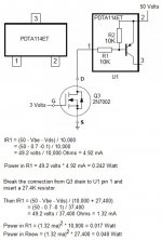
For U1 I have done some further calculations shown in the diagram below. The 2N7002 is driven by 3 volts = Vgs and a Vds value of 0.1 volt is estimated with the device being fully turned on. U1 is connected to 50 volts and the output at pin 3 (collector) is left open. The goal is to calculate the power dissipation in the U1 resistors when Q3 turns on fully.
R1 takes nearly all of the power, about 1/4 Watt which is too much for the SOT-23 package. U2 and U3 use higher resistor values and don't have this issue. Note also that the datasheet says that the voltage at U1 pin 1 should not be more than 40 volts below pin 2. This may be a voltage breakdown consideration aside from power dissipation issues.
I used a brute force method of reducing power in U1 and reducing voltage across pins 1 and 2 by breaking the connection from Q3 drain and U1 pin 1 and inserting a 27.4K resistor. This leaves more than enough base current in U1 to allow it to saturate fully when turned on by Q3. With the change to R27 the collector current in U1 should be around 16 mA.
Regarding the R7 change, I do not notice turn off transients in my amplifier. The circuit does have a wide tolerance considering the 2N7002 gate threshold variation so one unit's behavior is no guarantee. The LTspice file I posted a while ago does examine turn off timing at the end of the transient simulation.
For U1 I have done some further calculations shown in the diagram below. The 2N7002 is driven by 3 volts = Vgs and a Vds value of 0.1 volt is estimated with the device being fully turned on. U1 is connected to 50 volts and the output at pin 3 (collector) is left open. The goal is to calculate the power dissipation in the U1 resistors when Q3 turns on fully.
R1 takes nearly all of the power, about 1/4 Watt which is too much for the SOT-23 package. U2 and U3 use higher resistor values and don't have this issue. Note also that the datasheet says that the voltage at U1 pin 1 should not be more than 40 volts below pin 2. This may be a voltage breakdown consideration aside from power dissipation issues.
I used a brute force method of reducing power in U1 and reducing voltage across pins 1 and 2 by breaking the connection from Q3 drain and U1 pin 1 and inserting a 27.4K resistor. This leaves more than enough base current in U1 to allow it to saturate fully when turned on by Q3. With the change to R27 the collector current in U1 should be around 16 mA.
Attachments
I have a PDTA144ET I could swap in but maybe I should wait for Andrew to test it.
The only concern is that the pin 1 to pin 2 voltage can approach -50 volts while the specification says -40 volts is the maximum allowed. The 47K resistors will reduce the power dissipation nicely and still provide enough base current to easily control the 16 mA output current. However without more information about the -40 volt specification it seems the addition of an external resistor might be a better solution.
I took another look at the data sheet. I think this is the limiting breakdown voltage of the resistor, while the +10V has to do with the reverse bias on the BE junction on the lower resistance value input types. Perhaps a series resistor would be a good option - some thing to consider in a future update.
Hi Guys,
So what, if any, further changes should I make? Do I need to change U1? Should I cut and install 27K resistor?
Thanks, Terry
So what, if any, further changes should I make? Do I need to change U1? Should I cut and install 27K resistor?
Thanks, Terry
Change U1 as per Bill_Ps suggestion to a PDTA144ET - 47 k PNP RET
The 27 k is probably a good idea - do it.
Change R7 to 18 k or 22 k (either one will do fine).
Change R27 from 2.7 k to 10 k
You should be good to go. But make sure redo the tests before you go ahead and assemble your amp.
If updated the stand alone errata doc and the circuit diagrams in the main build doc.
Shucks, I thought I had the PDTA144ET but I guess I don't. It will have to wait until the next Mouser order. I hate paying shipping for $4 worth of parts. I have boards coming for the Slewmaster and will be building some of it's variants. I order the SMD with that stuff.
Blessings, Terry
Blessings, Terry
Shucks, I thought I had the PDTA144ET but I guess I don't. It will have to wait until the next Mouser order. I hate paying shipping for $4 worth of parts. I have boards coming for the Slewmaster and will be building some of it's variants. I order the SMD with that stuff.
Blessings, Terry
If you add the 27K resistor between Q3 and U1, you can keep using the PDTA114ET for U1 with no problem. That's what I ended up doing.
If you add the 27K resistor between Q3 and U1, you can keep using the PDTA114ET for U1 with no problem. That's what I ended up doing.
Is this where you cut the trace?
Attachments
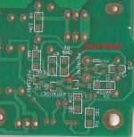
That is the right trace to cut. I did it in the middle of the 45 degree angled trace to center the resistor between other components. That was just to make the resistor placement and soldering easy.
I had to use a through hole resistor. I have hardly any SMD parts. Hopefully the PDTA change will take care of the problem so others won't have to cut traces. Be a shame if they have to make new boards. I have a 27k soldered in. I will test it tomorrow.
PDTA144ET still has the issue with 40 volts being the limit between pins 1 and 2. To fix that problem an external resistor is needed so the PDTA144ET does not provide a complete fix by itself.
I used a 0805 SMT resistor and it fit nicely on the bottom of the card. It's hard to tell that it wasn't designed that way.
I used a 0805 SMT resistor and it fit nicely on the bottom of the card. It's hard to tell that it wasn't designed that way.
I agree with Bill, as I've noticed all LED resistors run very very hot. 10K is a good choice for R21, R22 and R27 to keep things cooler if anything.
Calculate Pdiss of each resistor.
Then decide whether a single small resistor is upto the job, or if multiple small resistors are appropriate to the dissipation required.
Then decide whether a single small resistor is upto the job, or if multiple small resistors are appropriate to the dissipation required.
Another question: can we substitute PSMN4R3-80PS,127 for the PSMN4R3-100PS,127 on a one for one basis??? For some reason they are more available here than the later.
Will it affect performance?? Do some components need to be changed ???
Will it affect performance?? Do some components need to be changed ???
Another question: can we substitute PSMN4R3-80PS,127 for the PSMN4R3-100PS,127 on a one for one basis??? For some reason they are more available here than the later.
Will it affect performance?? Do some components need to be changed ???
If the amplifier is operating normally the MOSFETs turn on shortly after power on and don't see much voltage from drain to source. However there may be fault conditions that apply v+ to v- across the MOSFETs when we want them to be turned off. That would be close to 100 volts in the NX amp so I would not use 80 volt MOSFETs.
DigiKey does have the 100 volt parts in stock.
- Home
- Amplifiers
- Solid State
- SX-Amp and NX-Amp