That's mighty fine detective work, Bonsai, thanks for the revision.
I will make these changes even to the working boards I have so far. I think they will become a little more "forgiving". I am glad the PCB's are fine yet again a caution on reworking them: some pads and barrels are not too forgiving so be sure to inspect your final work to ensure good solder joints/contacts made on top and bottom of boards.
Jean
nx-Amplifier - Important Notice
If you have not assembled your boards yet, or you are having problems, make the following changes:-
R36 and R37 become 150 Ohms
R28 and R29 become 110 Ohms
R1 becomes 4.7k (but first read note below)
If you leave R1 at 10k, you will have around +-500mV of offset adjustment. I would suggest that you change R36/37 and R28/29 and then check the offset adjustment. If you cannot dial out the offset, then change R1 to 4.7k.
DIYAudio.com.
Wow, that is a pretty big change from 15R. Can't wait to try it.
Wow, that is a pretty big change from 15R. Can't wait to try it.
I did try it and now both boards blow fuses. Following the bring-up procedure there were 1 Amp fuses in the Vneg supply and an ammeter in the Vpos supply. I changed the Vneg fuse to 5 Amps and blew the 2 Amp fuse in the ammeter. Can't do any powered troubleshooting since there is evidently rather high fault current.
Here are the changes I made for this test: R36 = R37 = 150 Ohms, R28 = R29 = 110 Ohms. I tried both R1 = 10K and R1 = 4.7K with no difference. R6 adjustment pot was set to zero Ohms at the start of the test.
At this point I'm not sure what to do - Bonsai - suggestions?
Interesting. Do you have a light bulb tester? I would be good to know where the over amp is happening. I'll try switching those resistors in one board and see if I can get some measurements using the light bulb to limit current.
Can I suggest that if you have an amp which can already be adjusted to Vout = 0Vdc, you leave well alone. Dun fix wat aint broke.
But trying the new mod will help Andrew work out the bugs in da EVIL diamond input. 😀
But trying the new mod will help Andrew work out the bugs in da EVIL diamond input. 😀
Interesting. Do you have a light bulb tester? I would be good to know where the over amp is happening. I'll try switching those resistors in one board and see if I can get some measurements using the light bulb to limit current.
Thanks for the suggestion, that did get me past the problem. The light bulb tester kept the fuses from blowing and when I measured the supply voltage it was about half normal, +/-23 volts with a supply current of 223 mA.
The document for the NX amp says to start with R6 at zero Ohms but I found that as I raised the resistance the current went down. Setting the R6 pot at 1K Ohms initially allowed the amp to power up without incident. Then I was able to set the output current in the transistors and trim the output voltage offset.
The R6 adjustment is a bit touchy but the biggest change to the initial power up procedure would be to set R6 at maximum resistance, not zero. Now I should be able to make further progress in getting the amplifier fully operational.
Can I suggest that if you have an amp which can already be adjusted to Vout = 0Vdc, you leave well alone. Dun fix wat aint broke.
But trying the new mod will help Andrew work out the bugs in da EVIL diamond input. 😀
It plays but I'm not sure the front end and VAS are in the optimal current range. I plan to just make the changes to one board so I can compare.
Thanks for the suggestion, that did get me past the problem. The light bulb tester kept the fuses from blowing and when I measured the supply voltage it was about half normal, +/-23 volts with a supply current of 223 mA.
The document for the NX amp says to start with R6 at zero Ohms but I found that as I raised the resistance the current went down. Setting the R6 pot at 1K Ohms initially allowed the amp to power up without incident. Then I was able to set the output current in the transistors and trim the output voltage offset.
The R6 adjustment is a bit touchy but the biggest change to the initial power up procedure would be to set R6 at maximum resistance, not zero. Now I should be able to make further progress in getting the amplifier fully operational.
Thanks for highlighting this Bill.
I will recheck the doc to make sure I have the procedure right.
Probably get back later tomorrow. Another busy week for me.
Bill_P you are correct.
For Step 1 of the set-up procedure, R6 must be set for maximum resistance (1k) and NOT minimum . I've updated the errata doc and the write-up to reflect this.
For Step 1 of the set-up procedure, R6 must be set for maximum resistance (1k) and NOT minimum . I've updated the errata doc and the write-up to reflect this.
Hello, all. Did the mods to R28/R29 and R36/37 on my 3rd board just to see what happens - curiosity killed the cat. No not this time. Left R1 at 10k and could still dial out over 520 mV DC offset at first, no problem. Could also adjust Iq but did notice the 2SC3503's overheating during the adjustments, I mean really getting hot. Should this happen???
kgrlee maybe right!
kgrlee maybe right!
Hello jprco - no, they should not get hot - mine run cool. But, they are on the heatsink - are yours floating free?
The final test procedure states the following:
Measure between the amplifier boards 0 V and the chassis. You should measure 2 diode drops (switch your meter to the ‘diode’ function). Swap your meter leads around and measure again – you should also read two diode drops. This confirms that the ground lifter is wired correctly. If you do not measure this, you have a wiring problem – go back and check.
When I tried this measurement I got 22 Ohms resistance, not two diode drops. The power supply schematic shows R25, a 22 Ohm resistor, connected across the diode bridge clamp. Unless the test current is driven up above 60 mA, the diodes will not determine the voltage drop. Meters generally use 1 mA or so in diode test mode and will not indicate anywhere near two diode voltage drops at that current.
As I noted in a previous message, on the power supply I did have to change R7 to 20K to get the speaker protection MOSFETs to turn on. This change remains in my build and I wanted to be sure it was highlighted.
You are correct that with a conventional Ohms reading you will measure 22 Ohms. I will update the doc.
I will comment on R7 as well when I update the doc
Thanks for highlighting these points.
I will comment on R7 as well when I update the doc
Thanks for highlighting these points.
The nx-Amp document has been updated to reflect the changes to the diamond buffer degen resistors.
Note about R7 ( PSU +Protect board) also added.
http://hifisonix.com/wordpress/wp-content/uploads/2014/04/The-Ovation-nx-Amplifier-V2.0_8.pdf
Note about R7 ( PSU +Protect board) also added.
http://hifisonix.com/wordpress/wp-content/uploads/2014/04/The-Ovation-nx-Amplifier-V2.0_8.pdf
Hi Guys,
I swapped out the resistors. I still needed to lower R9. I just piggy-backed another 10K resistor onto the existing. That was enough to be able to dial out the offset. I've had the amp playing for a couple hours now. Sounds real nice. I just have one other issue that I think was covered but a search didn't expose the fix. On my PSU, D15 comes on instantly on power up. I believe there is supposed to be a delay. What should I look for to fix this?
Thanks, Terry
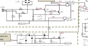
Check Q3 2N7002 for short circuit from drain to source. If that's ok, measure voltage from Q3 gate to source during power up. The voltage should rise slowly as C10 charges up. If the voltage at the gate snaps on maybe C10 has a bad solder joint.
Also check U1 pin 2 to pin 3 for short circuit (that's V+ to the junction of R3, R27, and R10).
Also check U1 pin 2 to pin 3 for short circuit (that's V+ to the junction of R3, R27, and R10).
OK, I checked Q3 and it takes about 4 seconds for charge up to about 1.25V. No shorts at U1. D15 get instant voltage when the switch is flipped. Would it help if I measure the voltages U1-3?
Thanks, Terry
Thanks, Terry
1.25V at Q3 gate to source is probably not enough to turn Q3 on. That's the voltage I had and had to change R7 to 20K to get the circuit to work. However in your case since D15 is on it implies that Q3 is on as well.
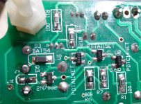
If D15 is on, then somehow U1 must be turned on. It might be helpful to measure voltages from all three pins of U1 with respect to ground (0V). Also confirm that the correct part is placed at location U1 - PDTA114ET (marked as 03).
U2 and U3 shouldn't have anything to do with the delay circuit not working correctly.
Last edited:
I gave every effort to place the proper devices. I don't have extras so I can't be sure now since the markings on them aren't the part number. I am attaching a small schematic with the voltages for each of the transistors in that circuit.
Thanks, Terry
Thanks, Terry
Attachments
- Home
- Amplifiers
- Solid State
- SX-Amp and NX-Amp