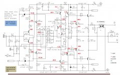
CRT driver BJTs "forever" gone....KSA1381 and KSC3503 had possibly been the only CRT drivers suitable for audio VAS as they did not show the drop in ft and hfe with rising emitter current but production discontinued no distributor has pairs with same suffix. Close is 3503 D and 1381 E and that's it. Thus one has two choices
take advantage of low Cob and accept disadvantage of unmatched hfe or choose another pair with much higher Cob but matching hfe...then you'll need cascoding.
So what to do?
Mismatch hfe in VAS is almost impossible to compensate so what are effects of Cob about 30 pF?
It should be well known that thd at max power at 20 kHz says almost nothing about sonic quality. Hi-end magazines publish distortion in terms of up to 7th harmonic at "musically significant" frequencies - about 10 at least- for power out from 50 mW to -3dB from max.
Many amps display surprising results as such that the harmonics spectrum varies unexpectedly thus that for ex. thd at 2 Watts is higher than at - 3dB. Many have large peaks of odd harmonics . This has not been observed with all tube amps. This was taken at a real load when loaded with a real passive multi-way speaker it gets worse . But again not with all tube amps. A way out was no global NFB.
I think these effects could be blamed on the not-at-all constant Cob of the VAS
Feedback after 2 1/2 months Sx use : very stable and musical, very nice wide and deep sound scene and pinpoint instruments placement (my LX521 3-way dipole speakers help for that too...)
(setup : 1 Tact digital amp channel for each of the 4 woofers, 4 Sx modules : one for each medium and each tweeter channel in dual mono setup)
So I am really delighted with the result. Thank you to everybody for the help, and especially to you Bonsaï for the schematics sharing and the accurate help too !
Francois
For D15 ( NX) is this Mouser 941-C566CRFNCTT0W0BB3 used special reason for that?
D15 is just an indicator LED. You can use any LED you want - I chose a green LED because to me a red LED indicates a fault.
schematic question
Hi,
I have a small question. The attached schematics are a bit different at input. I mean around the input signal ground via 15 ohm resistor & J2. Which one is latest?
Thanks
Farooq
Hi,
I have a small question. The attached schematics are a bit different at input. I mean around the input signal ground via 15 ohm resistor & J2. Which one is latest?
Thanks
Farooq
Attachments
Farooq, the write up on the website is the latest version and matches the PCB. Just download that and use it.
Feedback after 2 1/2 months Sx use : very stable and musical, very nice wide and deep sound scene and pinpoint instruments placement (my LX521 3-way dipole speakers help for that too...)
(setup : 1 Tact digital amp channel for each of the 4 woofers, 4 Sx modules : one for each medium and each tweeter channel in dual mono setup)
So I am really delighted with the result. Thank you to everybody for the help, and especially to you Bonsaï for the schematics sharing and the accurate help too !
Francois
🙂
On the NX amp and psu boards you see the 3,5 mm pitch Phoenix connectors.You also see 2,5 mm pitch 3pole connectors .Where can I find them ?
I only have found the 2,54 pitchl
I only have found the 2,54 pitchl
I see 5mm pitch Phoenix connectors, two position, on the power supply board only. The Mouser part number is 651-1985881.
The amplifier and power supply cards each have one Phoenix three position 2.54mm pitch connector. The Mouser part number is 651-1725669.
The amplifier and power supply cards each have one Phoenix three position 2.54mm pitch connector. The Mouser part number is 651-1725669.
These are not 2,54 mm pitch but 2,5 mm I'm shure about that .I've some 2,54 pitch connectors they are to big (housing) .They fit in but the surrounding parts can't be placed properly because of that issue .
These are not 2,54 mm pitch but 2,5 mm I'm shure about that .I've some 2,54 pitch connectors they are to big (housing) .They fit in but the surrounding parts can't be placed properly because of that issue .
Andrew , this is the problem doesn't look Nice
Refer to the PDF document "The Ovation nx-Amplifier" V2.09 for the following discussion.
On the amplifier board if jack J4 interferes with nearby components, probably C6 and C12, it is likely that you have chosen capacitors with excessively large diameter. See page 32 fig. 15 and page 35 fig. 20 for photos of the board with components populated. See also the overlay diagram on page 51. The BOM on page 48 indicates the capacitors C6 and C12 are Kemet ESH, 1000uF 16V, size 10mm diameter and 15 mm tall.
On the power supply board capacitor C4 is the only component near jack J10. The BOM indicates C4 is Nichicon UPV, 6.3mm diameter and 11mm tall.
I had no interference problems with the three terminal connectors when I built my NX amplifier using capacitors of the recommended size.
Hello Bonsai
Please excuse my intrusion here but I really would appreciate your input.
I have been reading your paper about the Ovation e-Amp that I do consider a case study.
Apart from several ideas that I already included in my power amp, I would also like to implement the very clever protection circuit (particularly the part that uses an optocoupler to sense output over current).
Would you please explain how it is done and what IC part you consider the best for this application ?
My power amp is described here.... http://www.diyaudio.com/forums/solid-state/297929-very-hq-power-amplifier-assemblage-vii.html
Maybe you have the time to take a look.... it is a basic blameless implemented with jfet IPS and laterals on the output. The layout was strongly influenced by your e-Amp and it sounds outstanding but apart from a temperature protection and output DC protection it does not have anything else so I am afraid that a short in the output that might happen eventually will cause serious damage.
Hello RC,
I use a FODM3053 random phase triac with the LED connected across a emitter sense resistor pair with a low resistor value divider. For an amp of c. 180-200 Watts the values are 100 Ohms in series with the coupler emitter LED and 47 Ohms across the emitter LED.
If the current exceeds the pre-set level, the triac tiggers (note: you must use only a random phase triac driver) and I use that to switch off a solid state relay via a Vishay VOM1271 photo-diode coupler. Do not use a standard relay because they generally cannot handle the kind of fault currents you will see if you short the speaker outputs on a big amp and they are also too slow for this technique.
I measured the response time from short circuit to solid state relay disabled (i.e OFF) of 100 uS on a 60A peak current on a new design amp. On the e-amp the figure is ~40 A peak before it trips.
I notice your amp does not have degeneration resistors (mosfet OPS). In that case you could sense the current in each rail and then drive some sort of latching circuit which in turn would drive the VOM1271.
Note that this type of protection latches the speaker relay OFF. You have to power down so that everything resets but I consider this a good thing in the case of an overcurrent condition.
I can drive my amps to full power, short the output and the solid state relay trips. I power down the amp and let it reset, power up and it works fine. The 10A slo-blo fuses in the rails are there purely for cases where there is a gross failure to prevent a fire hazard. They do not blow when I do the test I just described since the protection is much faster.
One final point, to test the current trip, load the amp OP with a 0.5 Ohm resistor in series with a 0.1 ohm current monitoring resistor. Feed the amp with a 1:10 pulse train with an ON time of 10ms. Monitor the OP current with a scope and adjust the lower divider resistor across the random phase triac until it trips at your desired peak output current
Hope this helps.
I build scaled down nx with 2*24V AC toroid for 2 way active speaker there is no requirement for short and SOAR protection but in very rare case of amp failure - high dc output voltage- a protection for the speakers could be useful . My solution is far from clever: a DC sensor triggers a triac which crowbars the supply via resistors. Not good for the elcos but simple. So far it has not happened and probably never will.
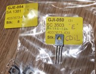
SC3503E and SA1381E from CDIL
CDIL also makes the SC3503 and SA1381 now, and the ones I just got (from www.reichelt.de) are all "E" bins. So that is good news for amp builders 🙂
I only bought 5 pcs each, just to verify if they were D or E, so it is a very small sample, but it looks pretty good so far: hFE 135-150, with most of them very close to 150. The KSA1381E I have from Mouser are all 146.
And since this is Bonsai's amplifier and thread:
I am very sorry to see that you have recently left the forum! 🙁 It is a loss for the community here, and I can only hope you will reconsider your decision.
Hi, can anyone tell me where I can obtain KSC3503 and KSA1381 with the same suffix for HFE in the UK.
I can get KSC3503D and KSA1381E easily but cannot find pairs with the same Hfe band. Bonsai has mentioned that they should be the same,
Any ideas please.
Alan
CDIL also makes the SC3503 and SA1381 now, and the ones I just got (from www.reichelt.de) are all "E" bins. So that is good news for amp builders 🙂
I only bought 5 pcs each, just to verify if they were D or E, so it is a very small sample, but it looks pretty good so far: hFE 135-150, with most of them very close to 150. The KSA1381E I have from Mouser are all 146.
And since this is Bonsai's amplifier and thread:
I am very sorry to see that you have recently left the forum! 🙁 It is a loss for the community here, and I can only hope you will reconsider your decision.
Attachments
- Home
- Amplifiers
- Solid State
- SX-Amp and NX-Amp