Thank you Niss_man. Appreciate the comments.
I wish I could upload more frequently, but given the time it takes to create the slides, recording and uploading, the frequency at which I am going is the best I can do.
Please don't forget to subscribe in Youtube. It helps me gauge interest in the channel.
Thanks again!
- Sandro
I wish I could upload more frequently, but given the time it takes to create the slides, recording and uploading, the frequency at which I am going is the best I can do.
Please don't forget to subscribe in Youtube. It helps me gauge interest in the channel.
Thanks again!
- Sandro
1. Progress/frequency
Please don't worry about that. I was just relieved to see you post again, especially with C-19 going on. You are orders of magnitude better than another favourite of mine: Project Binky. They post roughly every 3 months.
2. Interest
It is slow, yes, but this work is invaluable. I would say it is comparable in significance to Douglas Self's 8 Distortions articles and his subsequent book. Don't be discouraged by the numbers. Some efforts take a while to be recognised.
Thanks Shaun!
Interesting that you mention Dough Self's 8 distortion articles. Next video is on distortion. I just finished writing the script, so I now need to record it.
Saw the project Binky video. My uncle had a Morris Mini mini-minor just like that one, same color.
Interesting that you mention Dough Self's 8 distortion articles. Next video is on distortion. I just finished writing the script, so I now need to record it.
Saw the project Binky video. My uncle had a Morris Mini mini-minor just like that one, same color.
1. Progress/frequency
Please don't worry about that. I was just relieved to see you post again, especially with C-19 going on. You are orders of magnitude better than another favourite of mine: Project Binky. They post roughly every 3 months.
2. Interest
It is slow, yes, but this work is invaluable. I would say it is comparable in significance to Douglas Self's 8 Distortions articles and his subsequent book. Don't be discouraged by the numbers. Some efforts take a while to be recognised.
I completely agree. Sandro is doing an amazing Job and I for one really appreciate the content and the way he is presenting it to his audience.
Last edited:
5.1. Audio Amplifier Design: Introduction to distortion in audio amplifiers
Hi all, just to let you know that I just uploaded the next video of the series:
5.1. Audio Amplifier Design Fundamentals: Introduction to distortion in audio amplifiers
YouTube
The video is an introduction to distortion and it also list my own list of distortions in 2 stage audio amplifiers.
Topics in this video:
Distortion basics
- What is distortion?
- Distortion in the time and frequency domains
- How is distortion measured
Common distortions mechanisms
- Gain transfer plot
- The most common distortion types
- Odd and Even Harmonics
Distortion sources in amplifiers
- Systematic distortions
- Non systematic distortions
Next video: How to measure distortion using LTSpice
Hello Sandro,
I just wanted to say your videos on amplifier design are excellent and I thoroughly enjoyed them.
I want to post some questions to you about circuit design is it ok if I post on this thread.
I just wanted to say your videos on amplifier design are excellent and I thoroughly enjoyed them.
I want to post some questions to you about circuit design is it ok if I post on this thread.
Hi Phoenix, of course, it is a non-issue.
Also, I'll use this reply as an opportunity to share the outline of what is coming...
For Part 1: Audio Amplifier Circuit design, we have left:
- Finish distortion
- BJTs
- Noise
For Part 2: Audio Amplifier Circuit Design, I am thinking:
- Input stage design
- Feedback network
- Current sources
- Current mirrors
- Second stage design
- Output stage design
- VBE generator
- Output network
There will be a part 3 and 4 to cover topics including compensation, grounding, etc. But I have not planned them yet.
Best, Sandro
Hello Sandro,
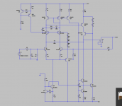
Attached is a function input stage which has the input bjt cascode. I feed the compensation cap as can be seen to the emitter of Q3 the for this is to improve the PSSR of the amplifier. The problem I have is the amplifier breaks into oscillation if I do not put some capacitors and resistors C3, and C4 plus R19 to stop these what I assume are parasitics this is done with trial and error is there a more analytic method. How do you simulate a solution to this problem so that dont use too much capacitance. I hope I have made my point.
I think the amplifier you design should include a PSRR spec the higher the better .
Attachments
Hi Phoenix, I'll sim it and get back to you. My hunch is that the minor loop is oscillating. See video 4.3, and do those tests: LGSA and LGSB. Look at the phase margin and gain margin of both loops. In you minor loop, you get delay from each cascode Q3 and Q16, these degrade the Phase margin of the minor loop and also tend to introduce weird behaviours at high frequency. If you can do those two bode plots, LGSA and LGSB, it would be very helpful.
Regarding the PSRR spec, I'll add it.
Best, Sandro
Regarding the PSRR spec, I'll add it.
Best, Sandro
Hi Phoenix, just to let you know I successfully simulated your circuit. Now I need to look for the problem.
Best, Sandro
Best, Sandro
Hello Sandro,
I simulated with single probe with 2 large caps on either side of the diff pair, it simulates the problem I have very clearly.
I am also interested in the solution comp caps you come up with, will put them in a and test them straight away along with my comp.
Thanks
I simulated with single probe with 2 large caps on either side of the diff pair, it simulates the problem I have very clearly.
I am also interested in the solution comp caps you come up with, will put them in a and test them straight away along with my comp.
Thanks
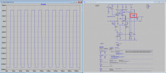
Hi Phoenix, so my only working theory is that there is too much delay in the cascodes. Therefore, what I did is by-pass Q3 with a capacitor C4 (see attached picture). I disconnected R19 and C3. Here is where things get odd. With 2pF, it oscillates, with 3pF it is very stable. Given such different behaviours vs. a tiny change do not happen in real life, and given that 3pF is a tiny tiny cap, there is something very strange going on here. Also I simmed it for 100 cycles to see delayed onset... nothing.
Need to investigate more. This is strange.
Need to investigate more. This is strange.
Attachments
Last edited:
Hi Phoenix,
Spent some time with your circuit. It is now clear that the problem is minor loop stability. This is a clear example of why doing the LGSA and LGSB simulations I show in video 4.3 are so important.
The issue is that you have 2 cascodes in the minor loop. Cascodes add delay which is hard to by-pass and degrade the phase margin on the minor loop. In your case, it got degraded enough to make it unstable.
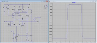
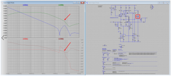
Screenshot_1: LGSA and LGSB of the amp without C3 and C4 (zeroed out).
- You can see that the LGSB has a phase margin of -30 degrees. Hence oscillation is expected.
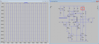
Screenshot_2: The resulting oscillation.
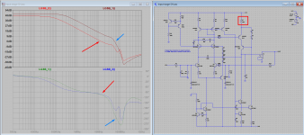
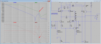
Screenshot_3: LGSA and LGSB with one cascode removed. The second stage one is removed. Phase margin in LGSB is now ~45 degrees which is stable.
Screenshot_4: The oscillation is gone. Note that I simmed 10 pulse cycles just in case.
Screenshot_5: I killed the BW of LGSB by increasing the degeneration of the second stage transistor Q14 by increasing R7 from 100 to 1k. Now the cross-over of LGSB happens with almost 80 degrees of phase margin.
Screenshot_6: Step response is oscillation free.
I hope this helps. Also I am attaching your circuit with the setup I used underneath. It is the same as in my videos.
Finally, regarding options, it is up to you. You can ditch the cascodes, increase R7, or add a lag compensator as you were doing. You now know what the problem is, and how to spot it, so you can make progress on your own. Again, the lesson here is to check the stability of the minor loop.
Best, Sandro
P.S. What is your first name?
Spent some time with your circuit. It is now clear that the problem is minor loop stability. This is a clear example of why doing the LGSA and LGSB simulations I show in video 4.3 are so important.
The issue is that you have 2 cascodes in the minor loop. Cascodes add delay which is hard to by-pass and degrade the phase margin on the minor loop. In your case, it got degraded enough to make it unstable.
Screenshot_1: LGSA and LGSB of the amp without C3 and C4 (zeroed out).
- You can see that the LGSB has a phase margin of -30 degrees. Hence oscillation is expected.
Screenshot_2: The resulting oscillation.
Screenshot_3: LGSA and LGSB with one cascode removed. The second stage one is removed. Phase margin in LGSB is now ~45 degrees which is stable.
Screenshot_4: The oscillation is gone. Note that I simmed 10 pulse cycles just in case.
Screenshot_5: I killed the BW of LGSB by increasing the degeneration of the second stage transistor Q14 by increasing R7 from 100 to 1k. Now the cross-over of LGSB happens with almost 80 degrees of phase margin.
Screenshot_6: Step response is oscillation free.
I hope this helps. Also I am attaching your circuit with the setup I used underneath. It is the same as in my videos.
Finally, regarding options, it is up to you. You can ditch the cascodes, increase R7, or add a lag compensator as you were doing. You now know what the problem is, and how to spot it, so you can make progress on your own. Again, the lesson here is to check the stability of the minor loop.
Best, Sandro
P.S. What is your first name?
Attachments

Hello Sandro,
Thankyou very much for your effort. I wil play with the setup you gave me.
In your experience is there much point to the cascode on the VAS when you buffer the VAS in terms of THD.
Thankyou very much for your effort. I wil play with the setup you gave me.
In your experience is there much point to the cascode on the VAS when you buffer the VAS in terms of THD.
Last edited:
If you use an emitter follower (EF) in the second stage like in the Honey Badger, I see no benefit from Cascoding.
Also, if you use a double in the OPS like in the Honey Badger, i.e. a two level output stage, then a an EF approach is superior to the cascode.
If you use a triple OPS, then the two approaches are comparable, the cascode may be slightly better.
I find it easier to work with an EF though.
Best, Sandro
Hello Sando,
Sorry I didnt read you email completely my name is Arthur.
With file above file should I be able to run that as is with your probe file lg_single.asc in the same directory. I seem to be not understanding something. I can get your file in video 4.3 working. I follow your probe files recommendations for use but something is not set up correctly.
Regards
Arthur
Attachments

Hi Arthur,
Having these defined in your plot.defs file will help:
.func lgsa() {-1/(1-1/(2*(I(LGSA:Vi)@1*V(LGSA:x)@2-V(LGSA:x)@1*I(LGSA:Vi)@2)+V(LGSA:x)@1+I(LGSA:Vi)@2))}
.func lgsb() {-1/(1-1/(2*(I(LGSB:Vi)@3*V(LGSB:x)@4-V(LGSB:x)@3*I(LGSB:Vi)@4)+V(LGSB:x)@3+I(LGSB:Vi)@4))}
.func lgsa2() {-1/(1-1/(2*(I(XT:LGSA:Vi)@1*V(XT:LGSA:x)@2-V(XT:LGSA:x)@1*I(XT:LGSA:Vi)@2)+V(XT:LGSA:x)@1+I(XT:LGSA:Vi)@2))}
.func lgsb2() {-1/(1-1/(2*(I(XT:LGSB:Vi)@3*V(XT:LGSB:x)@4-V(XT:LGSB:x)@3*I(XT:LGSB:Vi)@4)+V(XT:LGSB:x)@3+I(XT:LGSB:Vi)@4))}
For the setup you have, lgsa() and lgsb() is what you need. lgsa2() and lgsb2() is for the case where the probes are 1 level down the hierarchy.
Best, Sandro
Last edited:
- Home
- Amplifiers
- Solid State
- SW-VFA-01: Audio power amplifier video series