Some remarks:
- acceptable linearity of inductance of these chokes is because of air gapping;
- "reading" the DATS measurement the inductance at 20 Hz is about 160 mH, dropping to about 60 mH at 5 kHz; this is perfectly normal as the core looses permeability when going up in frequency;
- the DATS measurement is without DC current applied; real inductance in the amplifier might be different (can you show a picture of the air gap?); therefore
- core saturation behavior must be checked in a working amplifier to check if these chokes are able to do the job;
- stacking of these chokes looks sloppy.
I agree the plates are not perfectly aligned or sloppy. I wonder why they were not squared up before the bolts tightened and varnish or did they come loose during shipment. It was a long journey from Shenzen to Colorado to Virginia.
The plot is raw impedance in Ohms vs Hz. There needs to be a conversion to mH.
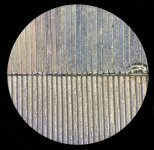
Air gap was specified at 0.1mm and I believe wax paper was used as the gap setting shim. It’s hard to see where it is though.
The only way to do this is to run it at full bias current and do a frequency response measurement.
Last edited:
The conversion to H is simple:
the curve shows 20 ohm at 20 Hz.
As the formula is H = reactance / (2 x pi x F), inductance at 20 Hz is ~ 160 mH.
At 5 kHz the curve shows 2k, that is 63 mH.
The specification of the manufacturer seems correct (60 mH @ 10 kHz), but, once more, this is an inductance meter measurement; practice might be different.
Picture of airgap??
Last edited:
Ah got it (balanced choke for push pull amp)
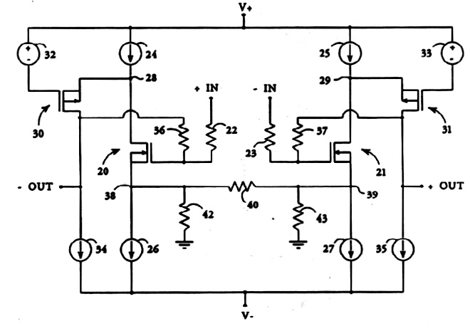
This is X's SuSyLu thread so my post was about the possibility of using the LL1694s in a low power version of his design - at least superficially X's shematic and new balanced inductors appear to me to be similar to common mode but I admit my understanding is limited. If my understanding is correct each winding of the inductor will measure around 80mH and 0.9ohm DCR - not too bad, though current would be limited to around 1.5A but perhaps that is sufficient in a low power context?
Each winding of the inductor will measure 40 mH (not halve of 160 mH but a quarter).
When used as balanced choke the DC currents will cancel so theoretically the choke could do without air gap.
When used as balanced choke the DC currents will cancel so theoretically the choke could do without air gap.
The conversion to H is simple:
the curve shows 20 ohm at 20 Hz.
As the formula is H = reactance / (2 x pi x F), inductance at 20 Hz is ~ 160 mH.
At 5 kHz the curve shows 2k, that is 63 mH.
The specification of the manufacturer seems correct (60 mH @ 10 kHz), but, once more, this is an inductance meter measurement; practice might be different.
Picture of airgap??
Thanks for the info on the conversion. I am glad the manufacturer got the spec right for 10kHz. 160mH at 20Hz is a nice value.
I will see if I can get a photo of the air gap.
The manufacturer told me that the laminations moved during transport. It must have gotten a pretty good knock during transport. I think if they had been bolted to a piece of plywood inside a box that would be the ideal way to transport them.
Here is a photo of the airgap under a microscope. I compared with a 0.127mm thick feeler gauge and this appears approximately 0.10mm gap. It’s not consistent though. Maybe there is a shim inside or maybe this is not the the airgap. I am checking with the manufacturer to see if this is air gap.

Here is a photo of the airgap under a microscope. I compared with a 0.127mm thick feeler gauge and this appears approximately 0.10mm gap. It’s not consistent though. Maybe there is a shim inside or maybe this is not the the airgap. I am checking with the manufacturer to see if this is air gap.
Attachments
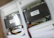
Here is a photo of the inductors prior to shipping. Looks like they got banged up pretty good despite the foam packaging. Note the laminations are all even. I am told when these ship in bulk by sea, there should not be any issues.

Attachments
Last edited:
Each winding of the inductor will measure 40 mH (not halve of 160 mH but a quarter).
Are you sure? The LL1694 has two windings and the datasheet states that the inductance is 160mH when they're connected in series and 40mH when they're connected in parallel. That tells me that each winding is 80mH,

When used as balanced choke the DC currents will cancel so theoretically the choke could do without air gap.
Fine in theory but my LL1694s are manufactured items so its irrelevant with them.
Yes,I am sure.
One winding measures 40 mH.
Two windings parallel also measures 40 mH as the number of windings (better to speak in "turns") does not change.
(this is basic knowledge...)
One winding measures 40 mH.
Two windings parallel also measures 40 mH as the number of windings (better to speak in "turns") does not change.
(this is basic knowledge...)
I think this is because they are wound on same core. If two separate and independent cores then the formulas of the series/parallel calculator apply.
But DCR is halved for parallel.
But DCR is halved for parallel.
(this is basic knowledge...)
Of course it is, just like all things that we think we know about...
Regardless, I was asking about whether the LL1694 willl serve to explore a version of X's SuSyLu in a context where 40mH may be sufficient, i.e. a full range speaker driver not required to do bass duty.
This may be a silly question, but... is there a way to replace the dual choke by some sort of a "dual CCS"? I guess it would be obvious to do this with a single choke in the SE version of the LuFo, what about the SuSyLuFo?
Rather silly yes ��.
The choke van be replaced by a CS, but you will have a different amplifier, and efficiency will drop dramatically.
The choke van be replaced by a CS, but you will have a different amplifier, and efficiency will drop dramatically.
I don't get it.
What would a "double CCS" circuit look like that acts like the dual choke in the AC domain?
(I understand that a CCS will need some DC drop to work, unlike a choke.)
What do you mean by "efficiency" in this context?
What would a "double CCS" circuit look like that acts like the dual choke in the AC domain?
(I understand that a CCS will need some DC drop to work, unlike a choke.)
What do you mean by "efficiency" in this context?
Check some Pass amps; F2 is an example of an SE amp with CS load (in the drain but the principle is the same). The CS needs the same voltage so these amps are max 25% efficiënt instead the 50% of inductive loading.
Basically, you are saying replace the choke with a MOSFET set up as a CCS, make two of those amps and connect the output nodes to the speaker in a balanced config without a coupling cap. Balance the bias currents so that net DC of zero volts across speaker load. The inductor provides energy storage and reactance to double the voltage swing. With a MOSFET CCS, there is no doubling so efficiency is less.
If you look at the F3, it is doing this and may be the amp you might want to check out. I think there are plans somewhere to clone the F3 but using LU1014D. The CCS is on top and the LU and cascode on the bottom. Still single rail. I would like to try this amp myself.

You could use something similar to Aleph topology so that the CCS has active push-pull and that can increase the efficiency. It may require an dual rail PSU now and it’s a completely different amp.
If you look at the F3, it is doing this and may be the amp you might want to check out. I think there are plans somewhere to clone the F3 but using LU1014D. The CCS is on top and the LU and cascode on the bottom. Still single rail. I would like to try this amp myself.
You could use something similar to Aleph topology so that the CCS has active push-pull and that can increase the efficiency. It may require an dual rail PSU now and it’s a completely different amp.
Last edited:
Well... I see your point as long as you look at the two symmetric sides of the SuSyLu amp as two independent sections. However, they are not. The two chokes wound on the same core work like 1:1 transformer that couples the two sections to each other.
My question is if there is a "coupled dual CCS" circuit that does what the dual choke (yransformer) does in the AC domain.
My question is if there is a "coupled dual CCS" circuit that does what the dual choke (yransformer) does in the AC domain.
Yes, good point. Needs cross coupling to be SuSy as discussed in first 10 posts of this thread. I think you basically go back to Mr Pass’ patent on the SuSy topology. It uses no chokes.
And we are back to the beginning. Alpha to Omega to Alpha. 🙂
And we are back to the beginning. Alpha to Omega to Alpha. 🙂
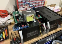
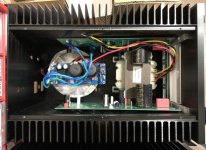
This is going going to be a tight fit to squeeze all this into this monoblock chassis.
Two LuFo boards (can skip the 10,000uF coupling cap), 400VA to 500VA toroidal trafo, a single rail SLB PSU for 6A continuous operation, the custom dual winding balanced choke, a SSR relay DC output protection board, a soft start board, and the VU meter driver board. The front end board will on mezzanine on the main LuFo boards. I hope it’s not too close to the power trafo.
Major components:

Shoehorned inside:

Each side will weigh about 45 lbs.
Two LuFo boards (can skip the 10,000uF coupling cap), 400VA to 500VA toroidal trafo, a single rail SLB PSU for 6A continuous operation, the custom dual winding balanced choke, a SSR relay DC output protection board, a soft start board, and the VU meter driver board. The front end board will on mezzanine on the main LuFo boards. I hope it’s not too close to the power trafo.
Major components:
Shoehorned inside:
Each side will weigh about 45 lbs.
Attachments
- Home
- Amplifiers
- Pass Labs
- SuSyLu Where Are You?