Magnetically induced eddy currents can be established in non ferromagnetic materials. They are simply present when there is a varying magnetic field. This is how aluminum, non magnetic stainless, and copper pans heat up on an inductive cook top stove. I think steel pans would heat as well but you might not be able to remove it from the stove when it’s on! 🙂
It’s also why full power 1kHz sine wave tests for 30min on the LuFo amp heat the MOT up to 55C vs 28C at 3A of DC.
It’s also why full power 1kHz sine wave tests for 30min on the LuFo amp heat the MOT up to 55C vs 28C at 3A of DC.
Last edited:
SS316 as you plan to use should be good enough. Consider the position of banding material is very close to the gap. Ferromagnetic band will try to concentrate magnetic flux leakage from the gap, saturate and gets hot. At least that's how I understand it.
Not sure, I have no experience with plastics for that particular use. Try it, easy enough to replace if it does not perform to your satisfaction.
The magnetic force is probably quite large and needs a metal clamp to hold it together. Also it can get warm. I wound hate to see the halves blow apart mid music.
Probably not. 🙂
Magnetic force actually pulls the two halves together. Problem of banding material with too much flexibility would be underdamp magnetostriction, the choke will become a noisy electromechanical transducer.
Magnetic force actually pulls the two halves together. Problem of banding material with too much flexibility would be underdamp magnetostriction, the choke will become a noisy electromechanical transducer.
Questions?
Hello xrk971 and all.
The [SuSy] patent of Mr. Pass continues to spawn ideas and schematics like in post#1. His great works are fascinating.
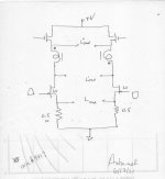
The attached and simplified schematic shows I moved the transformer from the sources [from post#1] to the drains of LUs.
Is this approach plausible and/or valuable to meet the [SuSy] objective?
Is there a similar value in moving the trafo to the drains of the Mosfets?
Best wishes
Anton
Hello xrk971 and all.
The [SuSy] patent of Mr. Pass continues to spawn ideas and schematics like in post#1. His great works are fascinating.
The attached and simplified schematic shows I moved the transformer from the sources [from post#1] to the drains of LUs.
Is this approach plausible and/or valuable to meet the [SuSy] objective?
Is there a similar value in moving the trafo to the drains of the Mosfets?
Best wishes
Anton
Attachments
The magnetic force is probably quite large and needs a metal clamp to hold it together. Also it can get warm. I wound hate to see the halves blow apart mid music.
?? How does that happen?
FYI non magnetic SS grade is 321 but you can use a big plastic wire wrap if you are worried.
I'm out guys.
An important question remains unanswered, and there is too much nonsense talk going on now...
Good luck with the project!
An important question remains unanswered, and there is too much nonsense talk going on now...
Good luck with the project!
Hi Daanve,
Not sure why you say it’s nonsense - my choice of going with C or EI core has been per your suggestion. I think I have a suitable clamping system for the core halves. People can discuss using nylon tie wraps but I am not going to use that - as nylon softens at temp and I know these inductors can get warm. I measured 55C when running full power sine wave tests on the LuFo inductor. A lot of questions about whether or not the clamp needs to be non magnetic are here but it’s a non issue if I am using 316SS band clamps.
Regards,
X
Hello xrk971 and all.
The [SuSy] patent of Mr. Pass continues to spawn ideas and schematics like in post#1. His great works are fascinating.
The attached and simplified schematic shows I moved the transformer from the sources [from post#1] to the drains of LUs.
Is this approach plausible and/or valuable to meet the [SuSy] objective?
Is there a similar value in moving the trafo to the drains of the Mosfets?
Best wishes
Anton
Hi Anton,
Thanks for your proposal of a new position for the inductor. I guess my question is what are you trying to gain by putting it here?
Note that the MOSFET is placed adjacent to the JFET to serve as a cascode to reduce the voltage seen across the JFET drain-to-source. The LU1014D is only rated to 20v. The MOSFETs take the brunt of the voltage drop and associated thermal dissipation and are sort of like a slave to the the little LU1014D which is the master. The LU1014D has special properties of triode like behavior and a high transconductance to give a very low output impedance (high damping factor) amp.
So moving the inductor up between the the cascode elements may negate or minimize the advantage one has with the special properties of the LU1014D JFET.
You should try to simulate it on LTSpice if you are curious.
Hi Daanve,
Not sure why you say it’s nonsense - my choice of going with C or EI core has been per your suggestion. I think I have a suitable clamping system for the core halves. People can discuss using nylon tie wraps but I am not going to use that - as nylon softens at temp and I know these inductors can get warm. I measured 55C when running full power sine wave tests on the LuFo inductor. A lot of questions about whether or not the clamp needs to be non magnetic are here but it’s a non issue if I am using 316SS band clamps.
Regards,
X
Plenty of plastic materials get use in transformers, including bobbin wrapping tape.
It doesn't need to be nylon either. A tie wrap melting is as likely as a transformer core 'pulling apart due to magnetic forces'.
Can someone show me a 600VA class core held together with plastic straps, zip ties, whatnot, then? If the clamp band is not sufficiently strong, or tight, the transformer would vibrate like a voice coil with the music. Microwave oven transformers are welded along the joint. They are very quiet.
I’m checking on cost for a custom dual primary balanced choke on EI core. Each leg would be minimum 60mH and maximum 0.5ohm DCR. Bifilar winding for perfect matching. 600VA-class EI GOSS core.
I got quotes for the custom dual primary EI cores. 60mH per winding and 0.50ohm DCR. I will order some samples to see if the whole SuSyLu concept works.
Hi X,
Just playing the devil's advocate. The concept of using a choke in the follower as a constant current source. It is also to store energy in the magnetic field to power the swing voltage. By hooking up this way to cancel each other's magnetic field, would it mean that there is no magnetic field and hence no energy storage....?
[emoji848]
Oon
I asked the same question but apparently from what I understand, this is a trick as old as the hills and is used by push pull tube amps. I think the way to think of it is that the although DC magnetic flux is cancelled, there is still AC magnetic energy and this is out of phase as the sides are anti-phase balanced drive and thus the AC field does not cancel and energy is indeed stored in there and that provides the AC reactance. It’s the DC that causes saturation.
Last edited:
- Home
- Amplifiers
- Pass Labs
- SuSyLu Where Are You?