Not sure about that. In a push pull amp, the DC fields are cancelled. However the energy input from the primary is driving the secondary. In this particular case, when the output is swinging negative, the energy is fueled by the collapse of the magnetic field. I am not if it is equivalent to push pull amp.
On a different way of looking at it is as if you are driving the inductor without a DC bias to the transistors.
Would it make any sense?
In any case, best of luck and do keep us posted.
Oon
On a different way of looking at it is as if you are driving the inductor without a DC bias to the transistors.
Would it make any sense?
In any case, best of luck and do keep us posted.
Oon
Susan Parker’s Zeus amp has been shown to work using a split primary toroidal inductor with no airgap. The only way this could have worked is if the DC field cancelled.
Zeus Amp - Toroid Transformer Version


Zeus Amp - Toroid Transformer Version
What I said is just a theory. I am uncertain of it as well. To me the topology is different using a choke to generate a negative swing versus in push pull where they cancel to generate an output on the other coil since it don't need to generate a negative swing. Only way is to jump in and find out.Susan Parker’s Zeus amp has been shown to work using a split primary toroidal inductor with no airgap. The only way this could have worked is if the DC field cancelled.
Zeus Amp - Toroid Transformer Version
Will be interesting to see your results. Let us know ja[emoji6]
Oon
I asked the same question but apparently from what I understand, this is a trick as old as the hills and is used by push pull tube amps. I think the way to think of it is that the although DC magnetic flux is cancelled, there is still AC magnetic energy and this is out of phase as the sides are anti-phase balanced drive and thus the AC field does not cancel and energy is indeed stored in there and that provides the AC reactance. It’s the DC that causes saturation.
That's exactly how it works.
I would be surprised if the air gap is actually necessary for the SuSyLu, since it's push-pull and the net DC flux is essentially zero. I don't remember seeing a push-pull tube amp that used a gapped transformer. Going with an ungapped transformer allows much higher inductance with the same core size, or using a much smaller core for the same inductance.
Sorry for coming back once more, but it seems necessary...
@ mbrennwa: that is how it works in theory but not IRL.
Guys, take the effort and read this:
output-trans-PP-calc-3A
Patrick (who sadly passed away shortly) perfectly explains why partial air gapping is needed for PP output transformers.
Once you understand a bit about u of transformer cores, and the relationship with DC magnetizing, you can start having a good discussion on what is needed for a quality choke (be it for SE or PP application).
Please note that Patrick also shows examples of transformer coupled mosfet output stages (with tube front ends); he refers to Susan Parker as well.
I got quotes for the custom dual primary EI cores. 60mH per winding and 0.50ohm DCR. I will order some samples to see if the whole SuSyLu concept works.
Did you got a good price?
Price at this point does not include being able to specify the air gap so I asking that this be revised. Price is good (under $60) if getting 200 units 🙂
Actually, we can specify airgap (0.1mm) and they will measure using LCR at 1kHz and guarantee that the measured inductance and DCR are in spec at 1kHz but not under DC load. The instrument to do that is very specialized and not part of their usual testing requirements.
Guys, take the effort and read this:
output-trans-PP-calc-3A
Patrick (who sadly passed away shortly) perfectly explains why partial air gapping is needed for PP output transformers.
Alright, if the DC currents through the two windings are not perfectly identical, there will be some DC magnetization. If the DC imbalance is too much, the core will saturate. I assumed the currents from the two amplifier halves would be nicely balanced when I said we don't need an air gap.
To allow some margin with the DC imbalance, a partial air gap may indeed be useful. The question would be if it's possible to make an inductor with a partial gap in order to get higher inductance than with a full gap, as needed for the SE LuFo amp. Higher inductance would be nice to improve the low-frequency headroom, so the LuFo clipping issues seen with low-frequency signals would be gone.
I also think the extra headroom that the SuSyLu has would also reduce the clipping issue due to depleted magnetically stored energy.
I should be receiving the 600VA samples in maybe 3 weeks. I have also asked pricing on 1000VA class EI core in case the 600VA sample is not enough.
I should be receiving the 600VA samples in maybe 3 weeks. I have also asked pricing on 1000VA class EI core in case the 600VA sample is not enough.
I now have a tracking number for the custom balanced EI choke. 🙂 hopefully will have it in a few days. I will need to build up a second channel quick though in order to try out the whole balanced SuSyLu operation.
The custom EI balanced chokes are finally here. The bifilar winding worked well as a DATS impedance sweep shows identical traces for both windings. They overlay almost perfectly. The factory measurement with their bench LCR was at 10kHz for 60mH. My DATS measurement is averaged over some frequency band and shows >100mH (greater than capability of DATS) and DCR registers circa 0.85ohm DCR. The important thing is that the impedance sweep shows a pretty much linear variation of the impedance vs frequency (on a log scale) and the phase is pretty much flat over the audio band. Whereas the same sweep of a MOT shows dips and wiggles in both the impedance and phase.
When I connect the two windings in parallel, the DATS still shows >100mH and the DCR drops down in half. So for a standard LuFo, this can be run in parallel for the loest DCR.
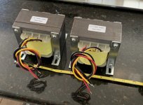
These are massive EI cores:

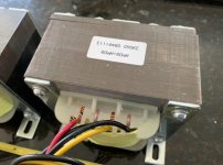
Closeup shows 14ga magnet wire:

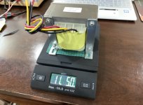
Weighs in at 11lbs 5oz each:

Here is the DATS measurment of both windings and they superimpose perfectly so you only see one color:

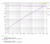
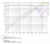
Here is a comparison of the custom choke (green) with a MOT (purple), notice the difference in linearity vs frequency:

When I connect the two windings in parallel, the DATS still shows >100mH and the DCR drops down in half. So for a standard LuFo, this can be run in parallel for the loest DCR.
These are massive EI cores:
Closeup shows 14ga magnet wire:
Weighs in at 11lbs 5oz each:
Here is the DATS measurment of both windings and they superimpose perfectly so you only see one color:
Here is a comparison of the custom choke (green) with a MOT (purple), notice the difference in linearity vs frequency:
Attachments
-
 CAB5FA9E-38F7-4565-8974-0E4AB003033A.jpeg442.1 KB · Views: 1,940
 -
 71AFBC67-860E-4D4A-A1C7-E271113B49CE.jpeg389.9 KB · Views: 537
 -
 C0E932BA-23B3-4512-B510-0A0676DE8698.jpeg419.8 KB · Views: 970
 -
 Custom-LuFo-Inductor-2-DATS-plot.jpg250.8 KB · Views: 2,080
 -
 Custom-LuFo-Inductor-2-MOT-compare-pot.jpg257.6 KB · Views: 533
Last edited:
It'll be interesing to see how this works out X - have fun!
Perhaps an obvious question is - SuSyLu-Lite?
My Lundahl LL1694 chokes can be used in common-mode configuration;
https://www.lundahltransformers.com/wp-content/uploads/datasheets/1694.pdf
Eliminating the output cap would seem like a worthwhile possibility for a low-power amp for efficient full-range speaker drivers.
The custom EI balanced chokes are finally here. The bifilar winding worked well as a DATS impedance sweep shows identical traces for both windings. They overlay almost perfectly. The factory measurement with their bench LCR was at 10kHz for 60mH. My DATS measurement is averaged over some frequency band and shows >100mH (greater than capability of DATS) and DCR registers circa 0.85ohm DCR. The important thing is that the impedance sweep shows a pretty much linear variation of the impedance vs frequency (on a log scale) and the phase is pretty much flat over the audio band. Whereas the same sweep of a MOT shows dips and wiggles in both the impedance and phase.
When I connect the two windings in parallel, the DATS still shows >100mH and the DCR drops down in half. So for a standard LuFo, this can be run in parallel for the loest DCR.
These are massive EI cores:
Closeup shows 14ga magnet wire:
Weighs in at 11lbs 5oz each:
Here is the DATS measurment of both windings and they superimpose perfectly so you only see one color:
Here is a comparison of the custom choke (green) with a MOT (purple), notice the difference in linearity vs frequency:
Some remarks:
- acceptable linearity of inductance of these chokes is because of air gapping;
- "reading" the DATS measurement the inductance at 20 Hz is about 160 mH, dropping to about 60 mH at 5 kHz; this is perfectly normal as the core looses permeability when going up in frequency;
- the DATS measurement is without DC current applied; real inductance in the amplifier might be different (can you show a picture of the air gap?); therefore
- core saturation behavior must be checked in a working amplifier to check if these chokes are able to do the job;
- stacking of these chokes looks sloppy.
Last edited:
Perhaps an obvious question is - SuSyLu-Lite?
My Lundahl LL1694 chokes can be used in common-mode configuration;
https://www.lundahltransformers.com/wp-content/uploads/datasheets/1694.pdf
Eliminating the output cap would seem like a worthwhile possibility for a low-power amp for efficient full-range speaker drivers.
You mean connecting the Lundahl choke as 1:1 output transformer?
Possible, but you'd have 40 mH of primary inductance and 0.9 ohm DCR of the primary and secondary.
Distortion and damping factor might become an issue.
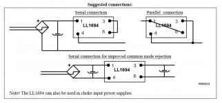
Ah got it (balanced choke for push pull amp); there will be a couple volts at each "leg" cancelling.
Inductance and DCR however remain something to consider.
When possible you could remove the air gap for more inductance (just leave a very small gap to accept some DC current unbalance).
DCR will not change.
Inductance and DCR however remain something to consider.
When possible you could remove the air gap for more inductance (just leave a very small gap to accept some DC current unbalance).
DCR will not change.
Last edited:
- Home
- Amplifiers
- Pass Labs
- SuSyLu Where Are You?