Hi Otto,
A couple of posts back I posted some video clips of a couple of tracks I use to listen for bass dynamics. One is the popular “Chocolate Trip” by Tool and the other is “Hey Now” by London Grammar which is very tough on an amplifier as it has infrasonic bass simultaneously with vocals. There are other tracks, one of my favorites is “Cornbread Fish & Collard Greens” by Anthony Hamilton, and another is “Man from Molise” by Pino Palladino and Blake Mills, and “Exit Chapel Perilous” by Tipper.
As far as comparing with my other amps, I am trying to box this amp up so that I can bring it over to the main rack to connect to the AB amp switcher box to do a fair comparison.
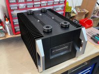
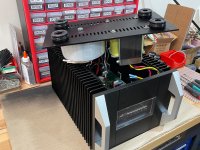
So packaging the amp tonight. I hate chassis work - but this one isn’t too bad. Most of the holes have been precut already. Some needed enlarging.
A couple of posts back I posted some video clips of a couple of tracks I use to listen for bass dynamics. One is the popular “Chocolate Trip” by Tool and the other is “Hey Now” by London Grammar which is very tough on an amplifier as it has infrasonic bass simultaneously with vocals. There are other tracks, one of my favorites is “Cornbread Fish & Collard Greens” by Anthony Hamilton, and another is “Man from Molise” by Pino Palladino and Blake Mills, and “Exit Chapel Perilous” by Tipper.
As far as comparing with my other amps, I am trying to box this amp up so that I can bring it over to the main rack to connect to the AB amp switcher box to do a fair comparison.
So packaging the amp tonight. I hate chassis work - but this one isn’t too bad. Most of the holes have been precut already. Some needed enlarging.
Last edited:
You better start working out in the gym because these beasts are HEAVY METAL. 🙂
Deceptively compact yet dense.
Deceptively compact yet dense.
I have not seen you case up most of your projects. My hat is off that is a piece of artwork.
Bill
Bill
I wonder how hot they run. 28 VDC rails at 2 x 3 amp means about 170 W of heat, and the chassis is not huge (260 x 200 x 363 mm). Do you need a fan, or is passive cooling good enough?
Also, those analog meters at the front are kind of retro cool in a good way. Do they actually work well?
It's good to know the DC blocking caps at the output are not necessary. I guess it's still a good idea to put a DC protection SSR between the amp output and the speakers.
I've got the LUs. I've got a bunch of SLB boards and parts. I could get the chassis from Ali. Can I get the dual choke? And the SuSy boards? And the front end?
It seems we have this question all the time.
If you agree that a single LuFo is SE Class A, then two of them are still SE Class A all the time. Balanced operation doesn’t change that.
X,
To be clear, I respect and admire your efforts, but at the same time you continue to spread nonsense about the SE vs. PP issue.
In short, the topology of your amp is nothing new and well known, and once and for all, it is considered to be push-pull. Any hint of it being SE is incorrect.
The elegance of the design is it's simplicity by inductive loading of the output stage, and it is therefore very comparable with the (same) simplicity of tube amplifiers.
I suggest you to read this blog which gives you all the information needed to update your knowledge (and to debug your former remark that push pull output stages need + and - power rails):
index
I wonder how hot they run. 28 VDC rails at 2 x 3 amp means about 170 W of heat, and the chassis is not huge (260 x 200 x 363 mm). Do you need a fan, or is passive cooling good enough?
This is a useful tool to check heatsink capacity:
Heat Sink Size Calculator
For 20 degr ambient and 50 degr max heatsink temperature these monoblocks are fine with some 85 watts dissipation for each heatsink.
Last edited:
Hi X,
Great effort on the SuSyLu build!
I have several 279mm x 279mm, 50mm fins + 7.5mm base thickness heatsinks availible. Would a pair of them work for a maybe 75W mono block?
Regards,
Cambe
Great effort on the SuSyLu build!
I have several 279mm x 279mm, 50mm fins + 7.5mm base thickness heatsinks availible. Would a pair of them work for a maybe 75W mono block?
Regards,
Cambe
@Wirewiggler - thank you! Case work is a pain in the neck, which is why I hardly ever put an amp in a case. I was up all night doing this even though most of the cutouts are there, the installation of everything is like a 3D jigsaw puzzle. One good thing about this case is you can assemble everything with all the panels flat. Then screw them together since all screws are accessible from the outside. I just had to connect a few Fastons onto their tabs at the soft start board (but could have been done ahead of time).
@Mbrennwa, the boards, front ends etc will all be available Gerbers for free, and I’ll have some in my shop if you don’t feel like ordering your own boards. I’ll post the Gerbers as soon as we verify operation. The balanced choke is a special order item. They are expensive if you make only two. I’ll have to think about how we can get more chokes made if there is enough interest.
I am not using any fans for the assembled chassis. I had them when they were lying flat on the bench. I have not connected the VU meter yet, but I’m sure they work nicely as visual indicators with a nice glow light in the back. The driver board has pots for setting the gain. Not sure I would rely on it to show how much power is delivered though. More of a visual effect thing.
@Cambre, My heatsinks are 350mm long x 200mm high x 40mm deep fins with 10mm thick baseplate. It is running at 48C for 25C ambient temp. So that’s 23C rise. 3.1A x 28v is 86W. Based on that, my heatsinks appear to be 0.27C/W rating. That’s very good for a passive radiator. If 55C is the max safe temp I could tolerate 30C rise or 110W max dissipation per side.
Last edited:
Hi Cambe,
I didn’t get a chance to estimate your heatsink vs mine.
280mm x 280mm is 78,400 mm square.
350mm x 200mm is 70,000 mm square.
Yours is 1.12x more area and fin is 70mm/40mm or 1.75x longer. The effect is probably not linear but definitely better than 40mm. Maybe 1.25x more?
So 1.12 x 1.25 is 1.40x more than my heatsink.
I don’t think you will have any issue using your heatsink. You might be about 0.20C/W rating.
One good thing about this case is you can assemble everything with all the panels flat. Then screw them together since all screws are accessible from the outside.
One more reason to go with this chassis!
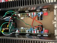
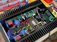
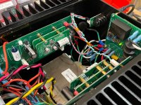
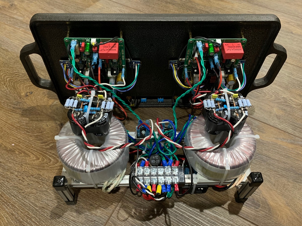
I’m chasing down the buzz/hum noise in the amp. I suspect it’s from the EMI radiated from the main toroidal power transformer and that is getting on the input stage. So I decided to test this out by flipping the positions of the inductor and power trafo. Luckily this amp is symmetric with respect to the floor board and screws accessible from the outside. Putting thr amp upside down then flipping the floor board 180 deg. I took the opportunity to clean up the wire routing.

The feet come in handy as handles to pick up the floorboard from the main chassis body:

Here is the amp reassembled with toroidal trafo in front and balanced inductor in the back:


The noise went down from 1.4mV rms to 0.9mV rms. Still there but looks like it’s coming from the toroidal trafo. A SMPS might be the only way to fix this.
The feet come in handy as handles to pick up the floorboard from the main chassis body:
Here is the amp reassembled with toroidal trafo in front and balanced inductor in the back:
The noise went down from 1.4mV rms to 0.9mV rms. Still there but looks like it’s coming from the toroidal trafo. A SMPS might be the only way to fix this.
Attachments
-
 C0C24BAE-7571-4231-8D01-0DBBE6B58AED.jpeg825.9 KB · Views: 429
 -
 24ACD8B4-AB1C-48D8-BF2F-2E0FB2B75A4B.jpeg770 KB · Views: 457
 -
 F57F0E3B-F0D4-451D-8DB7-4DBBB7B599D4.jpg484.6 KB · Views: 775
 -
 E61B6A1A-EDD5-4DDF-948C-E21F4EBDBB34.jpeg885.1 KB · Views: 424
 -
 E9687E0E-2F87-4EE1-BDD3-C90B76BE9FF6.jpeg704 KB · Views: 1,180
 -
 227EF034-2BC9-4A0B-9232-DFEC68C4BADC.jpeg818.5 KB · Views: 444
 -
 5DAB8933-0486-448D-8592-1F88CAA557B8.jpeg864.5 KB · Views: 770
Last edited:
The noise went down from 1.4mV rms to 0.9mV rms. Still there but looks like it’s coming from the toroidal trafo.
This is just a small change. Could be due to slightly different wire routing, or just a day-to-day variation. To teally check the influence of the transformer, I would remove the transformer and the SLB from the chassis and connect the DC rails using long leads to separate the AC power from the audio signals.
Yes, this ^
Then do what i recommended earlier – go for KEMET 24,000 uF, 40V per each PCB power rail inside the chassis.
Then do what i recommended earlier – go for KEMET 24,000 uF, 40V per each PCB power rail inside the chassis.
Oh, and since you have a hum problem, eliminate the complex relay based soft start module and replace it with a simple 4P terminal strip and a pair of MS22-20005 NTC thermistors wired into the primary side of the power transformer.
go for KEMET 24,000 uF, 40V per each PCB power rail inside the chassis.
Nothing wrong with adding a bit of real capacitance, but the SLB power supplies used in XRKs build will provide very clean DC already. I'd be surprised if the hum is from the power supply rails, but it's worth to check.
Oh, and if the hum turns out to be EMI, I wouldn't think that going with an SMPS would change this. The only change would be the frequency of the noise.
All good suggestions, guys. My next step was to bring trafo outside chassis. I’m quite sure that works as that simulates the flat splayed out arrangement earlier before I buttoned things up.
As this is a balanced amp, I think it also has the advantage of very good PSRR as the common mode noise in the power supply rails would be subtracted out due to the topology. It essentially looks like a big LTP input stage.
The EMI however is not going to affect both legs equally.
Things to try:
1. Bring trafo outside
2. Swap SFP soft start for basic heat burning NTCs on primary of trafo
3. Add bulk rail capacitance between PSU and amp
4. Use SMPS when it arrives.
SMPS does not have a massive winding that emits large scale magnetic flux leakage.
In addition to switching probably in 400kHz range that is inaudible, it has a very small transformer with much smaller size of magnetic field. I have done this in an M2 before and the EMI went away (thread here). The EMI here may be the proximity of the balanced inductor and the trafo. They are an inch apart. I think any amp with a transformer or inductor in the signal path may be susceptible to EMI pickup from nearby linear power trafo.
Sometimes I think making open frame amps with lots of room is the way to go if you want easy access and lots of cooling. I don’t have a problem with kids who touch my gear (they know better from training), perhaps one day a big Class A SuSyLu with a griddle (or two)? 🙂
Last edited:
- Home
- Amplifiers
- Pass Labs
- SuSyLu Where Are You?