Yes it is true ! the best result can be optained by choosing the right combination of Rk and the right load !
Further to that it has been shown that SRPP performs best with a high, fixed load that is optimized for lowest distortion.
Not a high load by any means. At a relatively low load (but a very specific one), there's a null in the distortion. MerlinB showed some very nice measurements of that in one of his articles, and I saw the same thing on the bench.
I think Merlin wrote that within an SRPP stage, due to variations within the same tube type, different tubes of the same type will find that lowest distortion null with different load values. Which would mean that you can't easily design the SRPP with a particular set of fixed R values and expect to hit that null with every tube you put in it. Right?
Right. First of all, the null usually occurs with a load that is slightly higher impedance than the simple equation predicts. If you design by maths alone you won't hit the null -you have to measure (it is better to make the load impedance too large than too small). Second, the null is narrow. A slight change in the load impedance, or in the valve characteristics, and suddenly you're not in the null anymore. The null probably changes with signal level too, slightly.I think Merlin wrote that within an SRPP stage, due to variations within the same tube type, different tubes of the same type will find that lowest distortion null with different load values. Which would mean that you can't easily design the SRPP with a particular set of fixed R values and expect to hit that null with every tube you put in it. Right?
You can see an example on page 298 of my book sample:
http://valvewizard.co.uk/DHFVP_sample.pdf
Last edited:
Not if the device models are so poor as to be almost useless.Koonw said:Spice simulation is as good as the person who uses it.
Spice knows exactly how to apply circuit theory to the components and circuit it has been given by a human. It can't, of course, know that the real components behave differently - but it seems that some designers don't know this either!This problem is well known so it is strictly not a Spice problem, spice won't know how to deal with all the look-alike circuits created by human.
Not if the device models are so poor as to be almost useless.
The model can be unless or has limited uses, agreed, but think it's more like "particular Spice model has fooled us", not "Spice has fooled us in a particular model" .
Last edited:
I have often wondered why your result for optimum SRPP load is slightly different from mine. You getMerlinb said:First of all, the null usually occurs with a load that is slightly higher impedance than the simple equation predicts.
Ropt = (Rk x (mu-1.5) - ra)/2
while I get
Ropt = (Rk x mu - ra)/2
- my formula gives a higher value than yours so it is interesting that you say in your book that the measured value tends to be higher than the predicted value. For the 6SN7 SRPP you calculate 750R but measured 1.2k. My value would be 1.5k, as it is always 0.75 x Rk greater than yours.
Anyway, I think I have just seen where your derivation differs from mine. You look for balance thus: "The circuit is balanced when the quiescent current is half the maximum or peak current which could ever flow through the triodes." My definition of balance is that each triode contributes equal amounts of signal current to the load. In reality these two criteria are probably not that different from each other, but because Ropt is the difference between two big numbers a slight change in balance condition gives a big change in Ropt.
A minor difference may be that you sometimes add an anode resistor equal to Rk but I don't. Perhaps you add this resistor to your calculation but not in reality? Could it be that in following the original inventor you have been led slightly astray? My experience is that the original inventor does not always understand his own invention as well as he thinks he does. For example, it was Raab who really explained how the Class E PA circuit works; not the Sokals who invented it.
Last edited:
I added the extra resistor in my old Audio Xpress article but, like everyone else, I don't use that resistor in practice and I abandoned it for my book. In my book I derive Ropt = (Rk x mu - ra)/2, same as you (exactly the same for the White cathode follower).I have often wondered why your result for optimum SRPP load is slightly different from mine.
A minor difference may be that you sometimes add an anode resistor equal to Rk but I don't.
Last edited:
Ok, so the discrepancy between calculation and measurement remains.
Scanning through that book sample makes me want to read it more closely, which may lead to me wanting to buy a copy!
Scanning through that book sample makes me want to read it more closely, which may lead to me wanting to buy a copy!
What is the nature of the residual distortion when the calculated value of Ropt is used? Second harmonic? Maybe the same snafu (non 3/2 power law) variation of Rplate is occurring there, as in the Aikido case.
Right in the null it will probably be third, as second will have cancelled out.
The mechanism of distortion cancellation is somewhat different for an optimised SRPP, as the optimum load is much smaller than the output impedance. The triodes are almost working into a short circuit so, unlike the half-mu stage (which relies on mu varying with current only), the optimised SRPP relies on balanced transconductance. This difference helps explain why measurements shows that SRPP has the expected null in distortion while the half-mu does not (except in simulation).
The mechanism of distortion cancellation is somewhat different for an optimised SRPP, as the optimum load is much smaller than the output impedance. The triodes are almost working into a short circuit so, unlike the half-mu stage (which relies on mu varying with current only), the optimised SRPP relies on balanced transconductance. This difference helps explain why measurements shows that SRPP has the expected null in distortion while the half-mu does not (except in simulation).
Correct. The problem is that SPICE models, and the simple theory, assume the internal anode resistance does not vary with voltage, only with current. <snip>
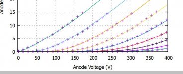
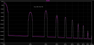
Apologies if I am being completely out of line here (I am new to tubes), but Merlin's lower curve (love your book by the way, an excellent read!) seems to imply that the Spice model predicts a constant Ra for all voltages. But if I plot the same for an 6Sn7 as an example, Ra varies with Va. This is a real plot of measured (graphic points from the uTracer) and simulated (solid lines):
Attachments
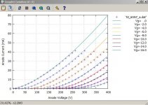
Merlin's lower plot is a Spice model for 12AT7, which looks too 'ideal'. You have shown a Spice model for 6SN7, which looks more realistic. Note that in both cases what has been shown is a Spice model, not the Spice model. For the more popular valves there are several Spice models, which vary in accuracy for anode curves and other matters such as grid current.
Right in the null it will probably be third, as second will have cancelled out.
The mechanism of distortion cancellation is somewhat different for an optimised SRPP, as the optimum load is much smaller than the output impedance. The triodes are almost working into a short circuit so, unlike the half-mu stage (which relies on mu varying with current only), the optimised SRPP relies on balanced transconductance. This difference helps explain why measurements shows that SRPP has the expected null in distortion while the half-mu does not (except in simulation).
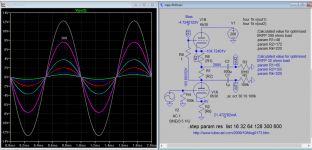
The following sims are based on SRPP+ All-in-One & Mu Followers
So it optimised SRPP, I plug in his optimised value for R1, R2 for 32 and 300 ohms load. The sim has predicted THD matched the calculation. ie. distortion is least at intended load.
Interested to know how much the actual measurement differed, distortion wise and any others if you know.
Attachments
Last edited:
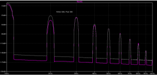
2nd harmonic is not canceled out as much once the load exceeded (greater than) the intended load, 3rd harmonic has little changes.
Attachments
Last edited:
Wow, I must be doing someting right! 😀Scanning through that book sample makes me want to read it more closely, which may lead to me wanting to buy a copy!
Even I agree with you! 🙂
I bought a copy and am reading it right now. Very good topic coverage, especially the bits on components. My personal experience agrees with what you wrote.
I would recommend this as one of those books you have got to have. Morgan Jones as well. So, for what it's worth Merlin, it's a very good work so far.
-Chris
Theory mixed with hands on DIY material.
Merlin,
I have a copy of your book sitting in front of me. I like that you have the right amount of theory mixed with hands on DIY material.
Starting in section 6.2 you lay out just how you made your distortion measurements with the AP-One audio analyzer and Rigol FFT. The typical audio analyzer will have loading issues with signal level pre-amplifier outputs. Your MOSFET buffer is on target
DT
Wow, I must be doing someting right! 😀
Merlin,
I have a copy of your book sitting in front of me. I like that you have the right amount of theory mixed with hands on DIY material.
Starting in section 6.2 you lay out just how you made your distortion measurements with the AP-One audio analyzer and Rigol FFT. The typical audio analyzer will have loading issues with signal level pre-amplifier outputs. Your MOSFET buffer is on target
DT
- Home
- Amplifiers
- Tubes / Valves
- Survey: Aikido distortion