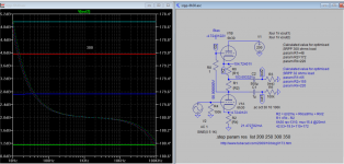
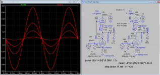
Here are plots for output level with load variation near optimal load and high load. At high load the output varies far less than near optimal load due load variation. Why some claimed it is not good for higher load??
Attachments
Right in the null it will probably be third, as second will have cancelled out.
The mechanism of distortion cancellation is somewhat different for an optimised SRPP, as the optimum load is much smaller than the output impedance. The triodes are almost working into a short circuit so, unlike the half-mu stage (which relies on mu varying with current only), the optimised SRPP relies on balanced transconductance. This difference helps explain why measurements shows that SRPP has the expected null in distortion while the half-mu does not (except in simulation).
Merlin, Dr. Dave or other DIY practionors,
This distortion canceling null for the SRPP circuit seems to work. Today I tested a breadboard for a optimized 12AU7 SRPP and measured a 2nd harmonic at – 76db. This is better, much better than a common cathode could ever be expected to do. There was no distortion canceling with the half-mu version. I know that this is a special case, everything needs to be just right.
There is a question here somewhere and here it is. Does this distortion last as the valves age? Does the distortion canceling notch shift with the ageing valves?
DT
This distortion canceling null for the SRPP circuit seems to work. Today I tested a breadboard for a optimized 12AU7 SRPP and measured a 2nd harmonic at – 76db.
At what output voltage?
Thanks. That's really not that remarkable for 1V. Certainly low enough to be inaudible, but not "better, much better than a common cathode could ever be expected to do."
You sure? Even with a CCS load a 12AU7 is not likely to get you -76dB @ 1V, and even an ECC88 wouldn't guarentee it. Of course, DT didn't say what the total THD was.
Last edited:
I had no trouble exceeding that with a CCS-loaded 6SN7. 12AX7 was even better. I haven't tried it with a 12AU7.
I would expect drift. The load for minimum distortion depends on the relationship between the upper valve characteristics and the upper cathode resistor, so this will change as the valve ages. I realise that I earlier saidDualTriode said:There is a question here somewhere and here it is. Does this distortion last as the valves age? Does the distortion canceling notch shift with the ageing valves?
but I think I may have got that wrong - I need to think some more. The condition for equal signal current from both valves does not include characteristics of the lower valve.DF96 said:The triodes are almost working into a short circuit so, unlike the half-mu stage (which relies on mu varying with current only), the optimised SRPP relies on balanced transconductance.
I would expect drift. The load for minimum distortion depends on the relationship between the upper valve characteristics and the upper cathode resistor, so this will change as the valve ages. I realise that I earlier said
but I think I may have got that wrong - I need to think some more. The condition for equal signal current from both valves does not include characteristics of the lower valve.
Dr. Dave,
The more I poke and measure these things the more I think. That is all good fun.
Perhaps the SRPP balances active devices against a fixed resistive load and the distortion canceling notch will drift over time or perhaps the valves will compensate for each other and the notch will not drift.
Interesting, the cognitive puzzle vs. empirical evidence, ultimately the thinking and evidence will merge.
DT
All,
12au7 optimized SRPP tested at 350 B+ volts. A bit of disclosure, the tube tested is a 9AU7 Amperex made in Canada, this one has an orange globe printed on it.
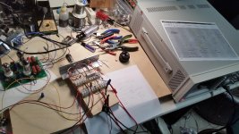
This Keysight N5752A is windows based, there is a sequence of pushing buttons and turning knobs I needed to be careful not to let smoke out of other items on the bench. This powersupply makes less noise than the Sorensen XT-250-0.250.
Output voltages and Harmonics listed below:
-1 Volt
-76.5 db 2nd Harmonic
-110 db 3rd Harmonic
-2 Volt
-70.5 db 2nd Harmonic
-103 db 3rd Harmonic
-5 Volt
-62 db 2nd Harmonic
-85 db 3rd Harmonic
-10 Volt
-56 db 2nd Harmonic
-73 db 3rd Harmonic
-113 db 4th Harmonic
-117 db 5th Harmonic
I have a nice NOS Phillips JAN 6DJ8 valve sitting here. Who wants to do the Merlin Optimized calculations and supply the resistor values for a 300 B+ volts supply? We will test it next.
DT
12au7 optimized SRPP tested at 350 B+ volts. A bit of disclosure, the tube tested is a 9AU7 Amperex made in Canada, this one has an orange globe printed on it.
This Keysight N5752A is windows based, there is a sequence of pushing buttons and turning knobs I needed to be careful not to let smoke out of other items on the bench. This powersupply makes less noise than the Sorensen XT-250-0.250.
Output voltages and Harmonics listed below:
-1 Volt
-76.5 db 2nd Harmonic
-110 db 3rd Harmonic
-2 Volt
-70.5 db 2nd Harmonic
-103 db 3rd Harmonic
-5 Volt
-62 db 2nd Harmonic
-85 db 3rd Harmonic
-10 Volt
-56 db 2nd Harmonic
-73 db 3rd Harmonic
-113 db 4th Harmonic
-117 db 5th Harmonic
I have a nice NOS Phillips JAN 6DJ8 valve sitting here. Who wants to do the Merlin Optimized calculations and supply the resistor values for a 300 B+ volts supply? We will test it next.
DT
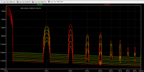
These sims indicated improved version 12au7 "A" has far less odd harmonics and THD. The optimised load is also somewhat different. To find out the opt load easy way is to measure the AC current in both tubes, adjust the load until they're equal.
Attachments
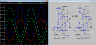
These sims indicated improved version 12au7 "A" has far less odd harmonics and THD. The optimised load is also somewhat different. To find out the opt load easy way is to measure the AC current in both tubes, adjust the load until they're equal.
Hello Koonw,
I took a closer look at your simulation attachments.
I am thinking about “improved” and “optimized” perhaps both words for better or best. So the question: better or best for what?
You attached simulations show the 12AU7 performing better than the reputation of the 12AU7. Your attachments show Harmonics close to my measured values.
I did not see the output voltage reported on your attachments?
DT
Last edited:
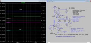
The voltage level is about 7.8V rms out.
Here are voltage level plot. To be get a fairer comparsion it maybe better to get the intended load constant (e.g one of 10k, 47k, 100K etc) then vary R1. Then the gains are also adjusted until they overlapped. Then we can more conveniently do the FFT for comparison. There must be a reason for improvement as many other tubes do improve over time, in reality you can hear the difference between different version, good or not is up to the listener to decide.
If any other FFT plots you need to analyse let me know
Attachments

Last edited:
I think if you do calculate it according to the book, in actual experiment you still need to ensure that it's at OPT condition. So see attached if any help for 6DJ8.
Edited R1B and Lev2
Edited R1B and Lev2
Attachments
Last edited:
At the risk of being called a Doubting Thomas, these figures look fishy to me. They aren't just good, they're implausibly good for a 12AU7 SRPP. Since the second harmonic is still dominant they imply you could get even better performance with a critical load. I would love to be proven wrong, but to be honest I smell an error somewhere.12au7 optimized SRPP tested at 350 B+ volts. A bit of disclosure, the tube tested is a 9AU7 Amperex made in Canada, this one has an orange globe printed on it.
Wow, I must be doing someting right! 😀
Maybe Merlin the magician ?.... 😀
I just bought your book. Great book . Just went through it quickly. Has lots of info I didn't know about.
At the risk of being called a Doubting Thomas, these figures look fishy to me. They aren't just good, they're implausibly good for a 12AU7 SRPP. Since the second harmonic is still dominant they imply you could get even better performance with a critical load. I would love to be proven wrong, but to be honest I smell an error somewhere.
Hello Merlin,
Skeptical is good.
Popilin posted a schematic, in response I built it. The first test was with a Sorensen XT-250- 0.250 power supply. The best it would do was 258 volts on the B+. I posted the results and a couple of voices wanted the full 350 volts on the schematic and higher output voltage so I connected the Keysight N5752A. With the B+ adjusted to 350 the breadboard was tested again at 1, 2, 5 and 10 volts output. I posted the results here.
Using the very same 9AU7 and U8903B analyzer I tested a half-mu breadboard and got much more pedestrian results.
See post number 68 at the below thread:
Survey: Aikido distortion
So what do you think? to put your Doubting Thomas to rest I think that someone else should test this “optimized” circuit!
You test and publish cutting edge insights, charts and graphs. I will be glad to package up all the mil-spec resistors, GE capacitor and the very same valve, all of it, and send it to you to test as long as you not use that Rigol oscilloscope to run the FFT’s.
Send me a PM with your mailing address.
All just for fun!
DT
Attachments
Last edited:
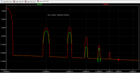
Here are distortion figures for 12au7a and 6dj8, they are very close under same load and ac current, 6dj8 could sound brighter judging from higher level of higher order harmonics, 7th, 9th for instance.
Attachments

- Home
- Amplifiers
- Tubes / Valves
- Survey: Aikido distortion