Thank you George, that is an interesting thread! I just remembered that Nelson Pass used big dual primary toroids as "plate chokes" in one of his Son of Zen versions. IIRC that was an LPT with a CCS in the tail, working as an balanced or self split output stage. Perhaps it could be done in a thirties style with a huge choke instead of the CCS... 🙂
I bought an E-I isolation xfmr from Jameco some years ago, made in China, cheap. I was doing some C measurements on some xfmrs then to determine usefulness for floating Circlotron supplies. I was alarmed at the high primary to secondary capacitance this xfmr had (like 1500 pf, can't exactly remember), so I took the end bells off to look. No insulation between primary and secondary, wire on wire. Aside from the safety issue for which one uses an isolation xfmr, one expects some capacitive isolation too. I measured a Magnetec N90MD medical isolation xfmr and got just 121 pF primary to secondary. At least an order of magnetude less. A Magnetec-Triad N-66A Isolation xfmr measures 320 pF (made in China). All models 250 VA.
I checked an Avel-Lindberg 135 VA toroid and got 20,000 pF from pri to pri (obviously bifilar primaries). And 878 pF from both primaries to both secondaries.
I also checked a Stancor TGC175-230 E-I. Four 120V windings but a split bobbin, 175 VA. 322 pF from primary to primary, on same bobbin side (stack wound). 82 pF from primaries to both secondaries, across bobbin sides. And 18700 pF from sec1 to sec2 on 2nd bobbin side (bifilar wind). With only 82 pF from secondaries to primaries, this model (2X) got selected for the Circlotron floating supplies.
I also measured an Edcor 100 Watt CXPP100-MS-1.7K OT and got 3450 pF from primary to secondary. I guess all the interleaving does that.
Also checked a Toroidy TTG-KT88PP 80 Watt 4K toroidal OT, 4000 pF from primaries to secondaries.
And a Toroidy TG-EL34PP 50/60 Watt 6.6K toroidal OT. 2680 pF from primaries to secondaries. Both models on the same size core.
Last edited:
I've been told the capacitance of the Toroidy's OPT are distributed on a very small part of the winding, so their effect on the bandpass is small.
I actually remember someone saying that toroidy transformers had poor frequency response which suggests otherwise.I've been told the capacitance of the Toroidy's OPT are distributed on a very small part of the winding, so their effect on the bandpass is small.
@Shoog : here you can find Bfpca that measured the opposite.
https://www.diyaudio.com/community/threads/el34-baby-huey-amplifier.326920/page-48#post-6458352
https://www.diyaudio.com/community/threads/el34-baby-huey-amplifier.326920/page-48#post-6458352
The Toroidy KT88-PSE's (1500 ohm SE) that I have are good (-3dB) to beyond 40 KHz. Antek's first foray into toroidal OPT's did have poor HF response. Don't know anything about their newer stuff, but some of the published graphs don't look great.
I measured the HF resonance for the Toroidy 4K and 6.6K PP OTs, both similar at 100 KHz. Using a Signal Gen with 10 K Ohms in series and a scope to look for the HF AC voltage dipping to a minimum. Measured between B+ lead and a primary end. (measured the same for either end)
I then checked the Edcor CXPP60-MS-4.2K and found the HF resonance at 45 KHz.
Also checked that Signal Corp DCP E-I 24 Watt xfmr 50/60Hz for HF resonance, and found 105 KHz. That only has enough turns for 6 Watts at 30Hz however.
On the low frequency end, the Toroidy 4K does 46.6 VAC across the 8 Ohm winding (using a
Variac and current probe) for an arbitrary acceptable level of saturation current spiking. For the same level of current spiking, the Edcor does 53 VAC across the 8 Ohm winding.
That would translate to LF of 32.3 Hz for the Toroidy (at 80 Watts) and 25 Hz for the Edcor (at 60 Watts). If the Edcor VAC is (arbitrarily, but bigger spiking ) increased to 65.3 VAC to get the specked 20 Hz at 60 Watts, and the Toroidy is increased by the same V ratio, the Toroidy would be at 26 Hz LF (80 Watt). And if the 80 W Toroidy were derated to 52 Watts it would reach the same 20 Hz LF limit as the Edcor. So roughly identical OTs, except for the doubled HF resonance for the Toroidy and the Edcor handling the LF end better.
My opinion. for acceptable current spiking at 20 Hz LF, both of these OTs are more like 40/50 Watt rating. For 25 Hz LF, both are roughly 60/75 Watt rating. Which just goes to show that you should always overate the OT Watt requirement some if you want real HiFi performance at the LF end.
Putting in the current derived Positive FDK fix (removing primary resistance and magnetizing current distortion feed-thru) could remove the Watt restrictions.
Last edited:

Thank you smoking-amp,
I've four Toroidy's OPT: one 4k 23%UL, one 6k6 23%UL and two 8k 23%UL.
Thank you for sharing where their real limits are.
I've four Toroidy's OPT: one 4k 23%UL, one 6k6 23%UL and two 8k 23%UL.
Thank you for sharing where their real limits are.
Conventional N Fdbk (V derived, local or global) would also allow using the full Watt ratings at the LF end too.
The Toroidy 4K PP (KT88) could also be looked at as a 3K to 6 Ohm OT for 80 Watt at 28 Hz.
The Toroidy 4K is clearly somewhat short on turns compared to the Edcor for the LF end. Like 0.88 the turns judging by the 8 Ohm Voltage readings for similar current spiking.
The Toroidy 4K full primary measures at 62 Ohms DC and the Edcor 4K OT at 260 Ohms for the full primary. The Toroidy still has plenty of primary inductance though due to the higher effective core permeability.
The 80 Watt rating versus the 60 Watt rating would also be expected to lower the primary Ohms by 3/4.
So taking into account the 0.88 V and 3/4 W factors: Apples to apples comparison would be 94 Ohms Toroidy versus 260 Ohms Edcor for exact same OT. The toroid config obviously saving copper, although the toroid seems a little oversized too, which would save more copper (square edges on the Toroidy, not a lot of wire there). Designs can trade off copper versus steel material.
Last edited:
late edit
the 0.88 V ratio above should be amended to 0.76 due to the higher V needed for 80 W versus 60 Watt at the LF end. So the Apples to apples compare would be 0.76 (V) x .75 (I) = 0.57. Giving 108.5 Ohms Toroid versus 260 Ohms E-I for equivalent OTs.
I would guess that most power type toroid xfmrs are not so heavily iron versus copper oriented as the Toroidy seem to be, They usually have a more round cross-section. You might see more like 1/2 the Ohms versus the E-I equivalent using them.
Last edited:
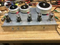
Time to get back to business after a long summer break. The big pair of toroids are resting on the shelf waiting for the energy crisis to be solved, in the meantime the smaller ones are actually playing music for the first time. My first attempt was with a pair of PL83 (15A6, N309, 15V heater version of EL83/6CK6) but they where a bit too weak for my taste and the load lines looked uncomfortably steep at 5,6k p-p. The mkII version uses PL36 (25E5, 25V version of EL36/6CM5) which allows 12W in the midband and 8W @ 40Hz and 4W @ 30Hz before the waveforms collapses due to saturation.
The output tubes runs at 250V B+ with 135V at the screen grids, minus the 15V drop across the cathode resistors (240R).
With 12AT7 LPT input stages and zero GNFB the voltage gain hits a slightly devilish x6,66...😈
The output tubes runs at 250V B+ with 135V at the screen grids, minus the 15V drop across the cathode resistors (240R).
With 12AT7 LPT input stages and zero GNFB the voltage gain hits a slightly devilish x6,66...😈
After failing miserably to use the smaller pair of toroids in a PL84 (~6CW5) amp, I've finally built something that actually works. Nothing wrong with the PL84s but the whole project was plagued by an aggressive buzzing sound that I couldn't get rid of, probably caused by diode noise from the rectified heater windings. When I found this big 230 + 28 VAC >150VA EI transformer for a good price I decided to tear the amp apart and rebuild it with AC heated PL36s (25E5) instead. This time I put the PSU in a separate chassis to get some extra distance between the mains transformer/choke and any parts that might be signal carrying parts. The whole effort paid off quite well, now I have a very good sounding amp with zero mechanical noise and very close to zero electrical noise/hum.
In fact it does sound so good that I almost regret using cheap sweep tubes (even if they have very nice triode curves) with these output transformers, I can't help thinking about how nice it would be to use 6S4S (russian 6B4G) instead🙂
The pair of bigger toroids from the beginning of this thread are still on the shelf, waiting for me to find a suitable power transformer for that project.
Congrats for the build ! I have a boatload of PL36 so I'm always interested in designs using them. What power do you get from this amp ?
Thanks! I haven't measured anything yet (been busy with other projects) but if it works as intended it should produce around 7W per channel, running the output tubes as triodes at ~235V 50mA each into 5,6k a-a. The tubes are running fairly cold, another 30V or so of B+ would be nice but I'm stuck with the power transformer I'm using. 10W in class A PP shouldn't be a problem from a pair of trioded PL36.
I keep thinking about the bit toroids from the beginning of this thread. IIRC they worked fairly well up to 25W or so and now I've found another big toroid with a multi-tapped 230VAC winding, very useful for a low-ish voltage, high current PSU. I also have over two dozens PL84s left from the failed project that was rebuilt as the much more successful PL36 amp, and some small toroids that could handle their heaters without messing with noisy rectifiers.
4x PL84 per channel should work nicely with 2k a-a at 200-250V with the sgreen grids fixed at 160V or so. The biggest challenge would be to build a phase splitter/driver stage that can deliver at least +-50V swing per phase from such a low HT rail.
4x PL84 per channel should work nicely with 2k a-a at 200-250V with the sgreen grids fixed at 160V or so. The biggest challenge would be to build a phase splitter/driver stage that can deliver at least +-50V swing per phase from such a low HT rail.
Why would you need that much drive? I ran 10EM7 power triodes off a 250 volt supply and the driver was able to supply the needed +/-37.5 volts. Not much to spare off the concertina, but it worked, cleanly. You need a bit more than half that to drive CW5’s. Sounded pretty damn good for an all cheap toroid amp.
Attachments
wg-ski: One of the more interesting aspects of those big toroids is that they have a set of secondaries that can provide 24% CFB to the output tubes. Probably enough to linearize pretty much anything but it puts quite a bit of strain on the driver stage instead.
Some ideas I've looked at so far:
* Adding an extra transformer or a 4X8 voltage doubler to boost the HT for the driver stage. Probably the best and easiest way to do it.
* Using plate chokes or Interstage transformers to allow the drivers to swing above B+. Expensive, and not a good solution if I would like to add some global negative feedback.
* Using a Mosfet Concertina phase splitter that can swing rail to rail.
I see… local feedback on the finals. With some schemes it needs more oomph than pure triode. I’d probably just add extra B++ if not much current is needed. Another surplus transformer and you’re in business (One that only cost five or ten bucks). Or a home brew wind job, which I tend to do. Even in normal pentode I’d end up doing that - separate plate, screen and bias voltages. Easy to add a higher B++ for a preamp if your already going to that trouble.
Mosfets can swing rail to rail, but if you don’t want coloration you need to keep 25 (sometimes up to 50) volts on them. To keep the capacitances from going horribly nonlinear, which is the reason for avoiding solid state in the first place. The usual 300 to 350 volt supply seems to be the reasonable way to go.
I was originally going to run CW5’s with those OPTs, but I didn’t want to spend the time to wind a custom power trafo at the moment. I had an off the shelf power trafo on hand that was perfect (maybe a bit oversized on VA) for running those horizontal amp triodes - in PP class A. Threw one channel together on the bench as an experiment, and later that afternoon started a full build. Now I’ve got to get another pair of those OPTs. Probably a couple more, at a different secondary voltage too.
Yes, a higher rail for the input/driver stage would probably be the best and simplest solution, and probably what I will end up doing.
I intend to run the output tubes "low and hot" at about 200V 60mA for about 14W of class A operation, fed by a 165V tap on the power transformer and filtered with a simple CLC filter. Not much voltage headroom for the drivers with that power power supply even though I possibly could get away with a Concertina phase splitter followed by a balanced pair of low mu triode drivers, like 12B4A or similar.
This would allow some interesting additional local feedback loops but adding a higher voltage rail and using two PC86s as an LTP input/driver stage would be less complex and probably sound better.
Been thinking a bit more about this subject. The power transformer has a high current 9,6V winding that I intend to heat the input/driver tubes with. PCF80 (9A8, or 6BL8 with a 9V heater) would fit the heater winding quite nicely (I have ten or twelve NOS Philips), and if I use a 4X8 voltage doubler to get a 400V rail I might get enough linear swing out of a Concertina DC coupled to the previous stage using that tube. If not, I could pick tubes that can swing closer to zero volts, like 6DJ8 for input and 12B4A for the Concertina.
One radically different idea is to use a pair of 10k CT/600R Edcor transformers wired backwards, driven by a chip amp or small class A stage. Highly experimental though...


One radically different idea is to use a pair of 10k CT/600R Edcor transformers wired backwards, driven by a chip amp or small class A stage. Highly experimental though...
- Home
- Amplifiers
- Tubes / Valves
- Surplus toroid transformers as OPTs...with a little twist.