Nice job!
I've got a question. To me, the circuits involving R3 and R16 looks as if you're supposed to remove the resistor only the channel with the highest DC offset. Is that about right, or are the resistor values (as provided) just so far off spec for a Tripath that its better to remove both resistors?
A while back, I had asked Sure to create an amplifier based on the Tripath--a natural choice because they're concentrating on class-D.
So, just recently I asked them to remove/omit R3, R16, C3, C24. And change/alter R8, R14 to 10k. And also add a couple more tank caps. Is that all okay?
What other tripath amps would you like to see? Um, let's not make it too difficult, because we might have to fix it. 😉
Hey, but the cool thing is. . . whatever you want, they'll just up and make it, in about 2 or 3 months.
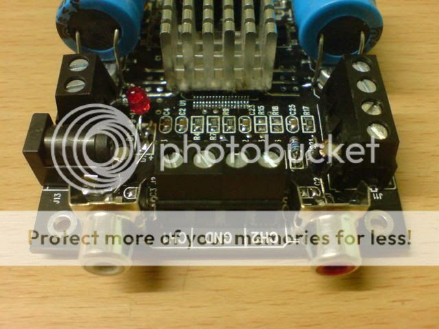
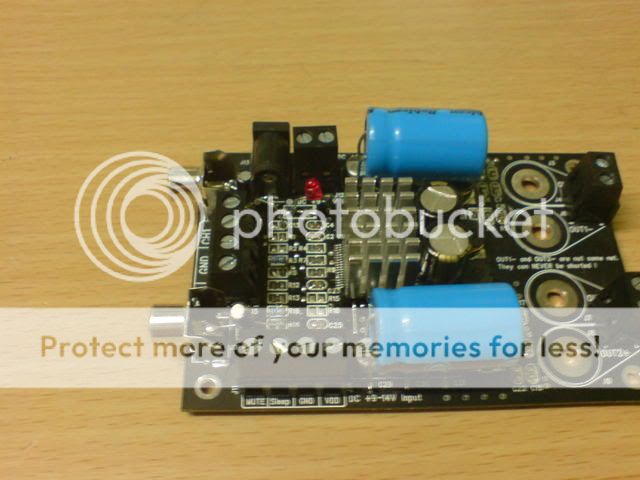
audio1st said:Here is a picture of a different board showing the power cap connection points..
Hey Audio1st
'litics on the inputs?..... I thought you were a staunch film man.....
And what is that on R15?......... looks like a trimmer
Lostcause said:
Hey Audio1st
'litics on the inputs?..... I thought you were a staunch film man.....
And what is that on R15?......... looks like a trimmer
Just a test board Lee😉 it is a trimmer, 50k, R15 & R1, very hard to adjust...Have to find a small multi turn next.
Trying to keep it all compact and on board.....less mess than my normal work anyway..
Output Voltage
When measuring the output voltage does it matter whether a source is plugged in or not? When I measure my stock 1.2 ver board I get 50mV at the speaker outputs. I am using a 12v 3.5a (42w) Samsung AD-4212L PSU with the board.
When measuring the output voltage does it matter whether a source is plugged in or not? When I measure my stock 1.2 ver board I get 50mV at the speaker outputs. I am using a 12v 3.5a (42w) Samsung AD-4212L PSU with the board.
Re: Output Voltage
50mv is fine. That's the usual DC offset on a sonic or the like.
And you should always check it un-loaded just in case it's too high and would damage your drivers😉
nbrophy said:When measuring the output voltage does it matter whether a source is plugged in or not? When I measure my stock 1.2 ver board I get 50mV at the speaker outputs. I am using a 12v 3.5a (42w) Samsung AD-4212L PSU with the board.
50mv is fine. That's the usual DC offset on a sonic or the like.
And you should always check it un-loaded just in case it's too high and would damage your drivers😉
Wildly inconsistent Output Voltage
OK I measured the output on my other three sureelectronics Tripath boards (all AA-AB012 Ver. 1.2 A41740). All reading were taken without an input source connected and each test was done multiple times with two separate Samsung AD-4212L PSU(s) and two different multimeters.
Here is are my results:
Board #1
J8 (+) & J7 (-): 39mV
J4 (+) & J6 (-): 20mv
Board #2
J8 (+) & J7 (-): 76mV
J4 (+) & J6 (-): -630mv
Board #3
J8 (+) & J7 (-): -980mV
J4 (+) & J6 (-): -825mv
Board #4
J8 (+) & J7 (-): -1620mV
J4 (+) & J6 (-): -1540mv
So what could be cause such a difference between boards? Should removing R-3 & R-16 bring the output voltage to tolerable levels in all cases? What could be causing the reversed polarity reading?
Hi nbrophy.
You, and Sure have been lucky with board #1. I would leave this board as it is, removal of R3 & R16 could give worse results..Board #2 is the worst balanced board and may benefit from the removal of one resistor..The other two should definitely benefit from the removal of both resistors..Definitely try with board #4 first..I would think 1.5V DC is unacceptable..
The DC will always be + or - 0mV to some degree....
R-3 or R-16
OK now I need to know which one of the resistors I need to remove for board #2. Looking at the schematic, I am trying to figure out which output corresponds R3 and which output corresponds R-16. I assume R3 goes to J4 & J6 output. Is this correct?
OK now I need to know which one of the resistors I need to remove for board #2. Looking at the schematic, I am trying to figure out which output corresponds R3 and which output corresponds R-16. I assume R3 goes to J4 & J6 output. Is this correct?
Re: R-3 or R-16
Hi nbrophy,
Yes R3 is correct. What are your new readings on the other boards. Did the #4 board drop a lot..?
Regards,
nbrophy said:OK now I need to know which one of the resistors I need to remove for board #2. Looking at the schematic, I am trying to figure out which output corresponds R3 and which output corresponds R-16. I assume R3 goes to J4 & J6 output. Is this correct?
Hi nbrophy,
Yes R3 is correct. What are your new readings on the other boards. Did the #4 board drop a lot..?
Regards,
Result of removing R-3 & R-16
Board #2
After removing R-3:
J8 (+) & J7 (-): 76mV
J4 (+) & J6 (-): -113mv
Board #3
After removing R-3 & R-16:
J8 (+) & J7 (-): -48mV
J4 (+) & J6 (-): 38mv
Board #4
After removing R-3 & R-16:
J8 (+) & J7 (-): 24mV
J4 (+) & J6 (-): -83mv
Board #2
After removing R-3:
J8 (+) & J7 (-): 76mV
J4 (+) & J6 (-): -113mv
Board #3
After removing R-3 & R-16:
J8 (+) & J7 (-): -48mV
J4 (+) & J6 (-): 38mv
Board #4
After removing R-3 & R-16:
J8 (+) & J7 (-): 24mV
J4 (+) & J6 (-): -83mv
Singing components?
Hi,
Here's a weird one: these amps are entirely solid state, correct? So what is it on mine that is producing music when no output is connected? Yes, it's quiet, and tinny, but there's definitely a reproduction of the input signal. I assume it's some kind of electromagnetic effect, perhaps the inductors?
Just curious, and wondering whether it might be a sign of a failure of some component or other that might cause trouble later on.
Chris
Power switch and LED
If I wanted to add power switch and LED to this board, how would I go about wiring it? I assume something would have to set up between my 12v 3.5a PSU and the board? Should I look for a particular value LED? Would I need a resistor to control the current?
If I wanted to add power switch and LED to this board, how would I go about wiring it? I assume something would have to set up between my 12v 3.5a PSU and the board? Should I look for a particular value LED? Would I need a resistor to control the current?
done!
after sometime of having this amp in my drawer.. i decided to do some mods with this little amp this afternoon.. so after an hour of work, here is the final results..
this are the mods ive done..
C21 & C13 replaced with 0.47uf Blackgates NX Hi-Q
C3 & C24 removed.
R1, R2, R3, R15, R16 and R18 removed.
R8 & R14 replaced with 10K 1% resistors
D1 removed and bridged.
2 Panasonic FM 470uf 16V added near chip.
2 Rubycon 4700uf 16V added on rails.
Power Led added
Heatsink added to the ta2024 chip
The DC offset of the stock amp is around 500-600mV for both channel. After removing R3 and R16 the dc offset was down to 44mV and 59mV.
Now for the sound... I can say that this amp really sound very good.. I'm using it with my wharfedale P-10 (86db) and he can drive it very loud..
🙂
after sometime of having this amp in my drawer.. i decided to do some mods with this little amp this afternoon.. so after an hour of work, here is the final results..
this are the mods ive done..
C21 & C13 replaced with 0.47uf Blackgates NX Hi-Q
C3 & C24 removed.
R1, R2, R3, R15, R16 and R18 removed.
R8 & R14 replaced with 10K 1% resistors
D1 removed and bridged.
2 Panasonic FM 470uf 16V added near chip.
2 Rubycon 4700uf 16V added on rails.
Power Led added
Heatsink added to the ta2024 chip
The DC offset of the stock amp is around 500-600mV for both channel.
After removing R3 and R16 the dc offset was down to 44mV and 59mV.Now for the sound... I can say that this amp really sound very good.. I'm using it with my wharfedale P-10 (86db) and he can drive it very loud..
🙂
Good job there xaudiox.
I'm in the same boat... having got two of these during the Christmas break I still need to take the bubble wrap off!
With 10K input resistors that's going to give you some considerable gain, no wonder it plays loud!
Certainly plenty of power available with those caps.
Note to self... get your finger out and the soldering iron...
I finally got around to finishing my case last night 😀 It still sounds lovely. Hopefully I'll post some pictures later.
(...still another 3 sat in bubble wrap)
(...still another 3 sat in bubble wrap)
An externally hosted image should be here but it was not working when we last tested it.
An externally hosted image should be here but it was not working when we last tested it.
...happy days!
The thing at the bottom is the amp, and on top is my little 3XTDA1543 NOS DAC.
Power Supply
After finding this little jewel, doing the homework, and reading every post in this forum, I have purchase one of these amps. My question is, which power supply to use. I have secured 2 laptop power supplies that should work fine, 12 v 3.5a & 15.6v 5a. Switching power supplies were discussed briefly earlier, and seem to work fine. The supplies set aside will be thrown on a scope to assure their abilities. But, should a classice regulated supply be considered? The supplies utilized by most other chip-amps seem like one option, as long as they are 12-13v. So, should one consider designing/building one of these jewels?
After finding this little jewel, doing the homework, and reading every post in this forum, I have purchase one of these amps. My question is, which power supply to use. I have secured 2 laptop power supplies that should work fine, 12 v 3.5a & 15.6v 5a. Switching power supplies were discussed briefly earlier, and seem to work fine. The supplies set aside will be thrown on a scope to assure their abilities. But, should a classice regulated supply be considered? The supplies utilized by most other chip-amps seem like one option, as long as they are 12-13v. So, should one consider designing/building one of these jewels?
- Status
- Not open for further replies.
- Home
- Amplifiers
- Class D
- Sure Electronics Tripath boards?