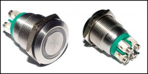
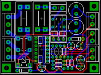
Thanks for that diagram Audio1st, I had been holding off buying one of these for ages but gave in at the weekend so it's on its way, that will save me a whole load of time digesting and redigesting the threads again.
Re: Re: Board Received.. Help
Thanks XaudioX. DC offset now -.6 Mv & - 12Mv.
Have just given it a continuous 48 hour "burn in" on a 30 amp power supply at 13.8 ( less input diode ) Volts. Diana Krall is starting to sound pretty good. Plenty of bass but top end not quite there yet. Looks like I need to get brave & start crushing a few more SMD's. Soldering to those Pads with Magoo eyes scares me.
I believe it likes more rather than less volts & is more dynamic at 13.8 V, though it could be the "burn in".
xaudiox said:
Yeah you need to remove R3 and R16 to reduce the DC offset to about 50mV.. I also did removed R1, R2, R15 and R18 on my amp..🙂
Thanks XaudioX. DC offset now -.6 Mv & - 12Mv.
Have just given it a continuous 48 hour "burn in" on a 30 amp power supply at 13.8 ( less input diode ) Volts. Diana Krall is starting to sound pretty good. Plenty of bass but top end not quite there yet. Looks like I need to get brave & start crushing a few more SMD's. Soldering to those Pads with Magoo eyes scares me.
I believe it likes more rather than less volts & is more dynamic at 13.8 V, though it could be the "burn in".
Re: Re: Re: Board Received.. Help
add more capacitance on the board.. 10000uf atleast.. 😀
ZL2BPS said:Plenty of bass but top end not quite there yet.
add more capacitance on the board.. 10000uf atleast.. 😀
It is on page 6 of the manual. But, 100mm x 66mm. Will not fit into an Altoids box. The smaller 8watt version may though. Snuff Box Amp!!!
Does anyone have the dimensions of this board? I'd like to put it in a mint tin.
Stop being a cheapskate!
 Once you've done the recommended modifications they truely deserve a decent box.
Off Topic
I don't think this warrants it's own thread, so I'm posting it here.
Here is another Ebay/Hong Kong/Tripath amp......
http://cgi.ebay.com/T-AMP-100WX2-Am...ryZ39783QQssPageNameZWDVWQQrdZ1QQcmdZViewItem
I don't think this warrants it's own thread, so I'm posting it here.
Here is another Ebay/Hong Kong/Tripath amp......
http://cgi.ebay.com/T-AMP-100WX2-Am...ryZ39783QQssPageNameZWDVWQQrdZ1QQcmdZViewItem
Re: Off Topic
almost sounds like too good to be true, higher output t-amp clone for under <$50?, will be interested in stock sound quality.
gychang
theAnonymous1 said:I don't think this warrants it's own thread, so I'm posting it here.
Here is another Ebay/Hong Kong/Tripath amp......
http://cgi.ebay.com/T-AMP-100WX2-Am...ryZ39783QQssPageNameZWDVWQQrdZ1QQcmdZViewItem
almost sounds like too good to be true, higher output t-amp clone for under <$50?, will be interested in stock sound quality.
gychang
I've ordered both anyway, I'll have to find some other box for the T amp...zayne742 said:It is on page 6 of the manual. But, 100mm x 66mm. Will not fit into an Altoids box. The smaller 8watt version may though. Snuff Box Amp!!!
Hey guys!
I got one of these yesterday and I measured over 1.2vdc on the output.
Tell me I am doing something wrong...please?
I just set the meter to DC mV and then had to up it to V and placed the +/- on each set of outs.
I did the same thing on original SI T-amp and got 110mv and 30mv and tried it on my Mouse and got 5mv give or take on each.
Is this the right way to do it?
Crap that is high.
Re: Re: Board Received.. Help
xaudiox said:
Yeah you need to remove R3 and R16 to reduce the DC offset to about 50mV.. I also did removed R1, R2, R15 and R18 on my amp..🙂
billnchristy said:Hey guys!
I got one of these yesterday and I measured over 1.2vdc on the output.
Latching circuit for NO momentary pushbutton switch
I would like to attempt to still use my normally open momentary pushbutton switch as a power switch for my amp.
I found the following article on how this may be achieved (http://www.edn.com/contents/images/102804di.pdf).
I am complete newbie when it comes to electrical circuits so bare with me. I am attempting to read up as much as I can comprehend.
The article mentions that at higher voltages applications may require a proportional increase in some of the resistor values. R2 and R4 should be left constant at 470k and 1k Ù respectively and R1 be increased to 4.7MÙ for 10v application (I assume also acceptable for 12v?). Will any of the other resistor values need to be adjusted for my 12v 3.5a application?
Also can someone give me some guidance on selecting the appropriate switching transistors for Q1, Q2, Q3, and Q4?
Thanks,
Nathan
The major underlying issue with using the momentary push-button, especially in that circuit, is noise! You will be running the risk of inecting unwanted harmonics into your power supply, and basically poisoning the well. My advice, if you were to stay on this path, is to go with a simple circuit, 555 timer comes to mind, with a straight pass through on a relay to assure a clean supply voltage. The only other option I see with a momentary, you could use it to put the amp into sleep mode, which should work like your normal off the shelf units. But, I may be mistaken about that one, do not have my amp yet to experiment. There are some very interesting latching relays on Digi-key. Trying to research it now, will let you know if I come up with anything. Maybe someone else has experience with these?
Got my board today, doing a dance!
nbrophy, there is more than likely a way to use the latching relays for your momentary switch. The big question is, how much would you like to spend? Right now, with the research done, it looks like you will nee $20-30 in parts. Relay, debouncing circuit, possible second relay.
nbrophy, there is more than likely a way to use the latching relays for your momentary switch. The big question is, how much would you like to spend? Right now, with the research done, it looks like you will nee $20-30 in parts. Relay, debouncing circuit, possible second relay.
Thanks for the help zayne742, but I could not bring myself pay more a then the amp itself. I am fond to the switch due to its nickel finish matched my nickel volumn knob.
You mention using my switch to put the amp into sleep mode. I was under the impression that the sleep and mute terminals of little use based on earlier posts.
You mention using my switch to put the amp into sleep mode. I was under the impression that the sleep and mute terminals of little use based on earlier posts.
Hi tobias_svensk,
Would it be possible to build-in a soft start delay?
This would then be a very useful addition to all T-amps..?
Would it be possible to build-in a soft start delay?
This would then be a very useful addition to all T-amps..?
I see no problem in building a softstart-board like he has in this link (Optional Soft-start Circuit @ the bottom)
http://maxhawk.flagshiphosting.com/projects/Ampturnonv2/index.htm
The softswitch-board he has (same as I was thinking of building) has a separate 12V on/off terminal that switches with the button.
So it could be done in two ways, an additional softstart board and you could get one relay on one board that switches right away and one relay on the other boards that switches after a couple of seconds. Or make one whole board that just has one relay that switches a couple of seconds after you press the button.
/T
- Status
- Not open for further replies.
- Home
- Amplifiers
- Class D
- Sure Electronics Tripath boards?

