Thanks Mark! My question though is, would this not be a better performing option?
It is a real question for me, as I am building a battery fed +/-18V regulator for my phono preamp. I have extra boards and parts and I want the best performance. Would using two positive boards be better in my case?
It is a real question for me, as I am building a battery fed +/-18V regulator for my phono preamp. I have extra boards and parts and I want the best performance. Would using two positive boards be better in my case?
Is there a way to get 1-1,5 A out from these Super regulators using one or more positive regulators for positive voltage?
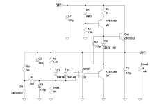
Yes. The current limit is defined by the current through R1 multiplied by the gain of Q1. To increase the output limit, you need to increase the current through R1 by lowering its resistance. The voltage on it is the LED voltage (1.7V depending on the type of LED, the input voltage, and the value of R2) less the emitter to base voltage of Q2 (approx. 0.7V) = 1V approximately. So the current through R1 roughly is 4mA. Assuming the gain is 100, the output current limit is 400mA. Also note that increasing the current will cause an increase in heating of Q1, so you’d need good heat sinks for cooling.
Disclaimer: I am a newbie, please double check with the experts if the above is correct.
Disclaimer: I am a newbie, please double check with the experts if the above is correct.
If you reengineer the circuit design, and arrange it to become compatible with higher power discrete transistors like the MJL3281A (NPN) and/or MJL1302A (PNP), and if you also modify the frequency compensation to ensure the revised circuit is stable, then: yes it is possible to get output currents of 1.5 amperes or more. It's a pretty big job and will involve quite a lot of calculations.
Mark, good point. However D44H11 by onsemi is 10A / 70W. A voltage drop of 5-7V and the current of 1A would use only 10% of this transistor capacity. In your opinion, what output current value would justify redesigning the circuit for a more powerful transistor? Thanks for your insight!
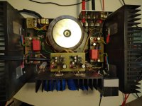
Four years ago I made the first 5A version, it took a bit of effort but it paid off in the end.Mark, good point. However D44H11 by onsemi is 10A / 70W. A voltage drop of 5-7V and the current of 1A would use only 10% of this transistor capacity. In your opinion, what output current value would justify redesigning the circuit for a more powerful transistor? Thanks for your insight!
I haven't taken them out of the amp (JLH69 or Le Monstre) since then, except that they are now quite improved.
Attachments
@grunf I love to see this 5 A improved schematic. 🙂Four years ago I made the first 5A version, it took a bit of effort but it paid off in the end.
I haven't taken them out of the amp (JLH69 or Le Monstre) since then, except that they are now quite improved.

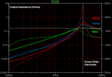
As the current increases the gain of Q1 increases...approaching 100mA you start to experience impedance peaking....MJL3281A DC gain is about 50% higher than D44H11 IIRC.If you reengineer the circuit design, and arrange it to become compatible with higher power discrete transistors like the MJL3281A (NPN) and/or MJL1302A (PNP), and if you also modify the frequency compensation to ensure the revised circuit is stable, then: yes it is possible to get output currents of 1.5 amperes or more. It's a pretty big job and will involve quite a lot of calculations.
The compensation is C3||R6 (120u||1k) and C4. For my simulation I plug in an ESR value of 120 milliOhm. Jan, in his 2015 schematic draws C4 across the output. Instead, decouple it via R16.
Last edited:
Can you please clarify what you mean by impedance peaking at 100mA? Thanks!
See the attached -- using output impedance and group delay you can approximate the stability. Look back a few pages and I showed the equations. The example uses AD825AR and D44H11.
Attachments
The new version is no longer so simple, now it has 13 transistors (10 SMD) and does not use any zener diodes or references. All parts of the schematic are not mine, so the publication will have to wait.@grunf I love to see this 5 A improved schematic. 🙂
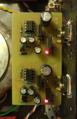
To begin with, I am attaching the first test version that I used in JLH69, instead of KTD2061/KTB1369, TTC004/TTA004 or the popular BD139/140 can be used.
Attachments
2SC5242 is hard to find and get.
2SC5242 is also known as FJA4313.
J-fet op amps enable much better performance of the regulator, especially if the value of resistor R4/11 is increased (up to 10k depending on the op amp itself and the used C9/10) in the RC filter.
Which type of op amp's input resistance, common mode or differential mode, allows increasing R4/11? For example, AD797 is known to perform well in the Super Regulator (if not oscillating). Its input resistance is 100 MOhm common mode, but only 7.5 kOhm differential mode. Can R4/11 be increased with this opamp, say, from 500 Ohm to 5 kOhm? Thanks!
It is not input impedance but opamp input current noise that makes a difference. Here is good explanation:
https://www.analog.com/media/en/training-seminars/tutorials/MT-047.pdf
With bipolar opamps as is AD797, large resistor at input will have more noise voltage produced by opamp input current noise passing through resistor, than is resistor thermal noise. Resistor is a part of RC filter, so noise will be attenuated, but we have a higher starting point.
JFET opamps have 1000x less input current noise.
For AD797 no ,because, like all bipolar op amps it has a much higher input bias current than jfet op amps, in combination with the high resistance of R4/11 it increases the error - voltage variations. For this reason capacitors with low leakage current are essential when using R4/11 with a resistance above 1k.Which type of op amp's input resistance, common mode or differential mode, allows increasing R4/11? For example, AD797 is known to perform well in the Super Regulator (if not oscillating). Its input resistance is 100 MOhm common mode, but only 7.5 kOhm differential mode. Can R4/11 be increased with this opamp, say, from 500 Ohm to 5 kOhm? Thanks!
Not yet, I have them at home but not enough free time.@grunf Any results with the low leak Nichicon caps you’ve ordered?
- Home
- The diyAudio Store
- Super Regulator