
hi i have built the regs with standard voltage of +/- 15v
whats the value of the 4 resistors for 24v using OPA604 ?
whats the value of the 4 resistors for 24v using OPA604 ?
I made a spreadsheet for this purpose. Enter the green fields. It gives you two options, If R6 is known or if R7 is known.
Jung SuperReg Calc - Google Sheets
You might need to copy it and paste into your own spreadsheet since the sheet is read only. Perhaps someone can confirm my math so I'm not spreading misinformation.
Jung SuperReg Calc - Google Sheets
You might need to copy it and paste into your own spreadsheet since the sheet is read only. Perhaps someone can confirm my math so I'm not spreading misinformation.
HTML:
https://docs.google.com/spreadsheets/d/1t5JT0aNAOV2WbWRPjG1K7J81KzBWZ6xl8D3r1ACIDgs/edit?usp=sharing
Last edited:
b4bz,
Your version of spreadsheet is "view only"
copying that spreadsheet did not make it work for me
glennjarrett,
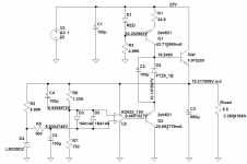
To get 24v I did the following:
D5 change from LM329 to LM4040-10
24V - 10V = 14v
14/10 = "Z"= 1.4
"Z" multiplied by R7 or R14 value = R6/R13 value
for
R7/R14 = 1K
R6/R13 = 1.4K
D2(pos) and D7(neg): change the zener from 6.8v to a 12volt
change to 35v caps
input of superreg needs to be 27vdc
Your version of spreadsheet is "view only"
copying that spreadsheet did not make it work for me
glennjarrett,
To get 24v I did the following:
D5 change from LM329 to LM4040-10
24V - 10V = 14v
14/10 = "Z"= 1.4
"Z" multiplied by R7 or R14 value = R6/R13 value
for
R7/R14 = 1K
R6/R13 = 1.4K
D2(pos) and D7(neg): change the zener from 6.8v to a 12volt
change to 35v caps
input of superreg needs to be 27vdc
Thank you Jan. I get it. This is great info, you probably spelled it out before in your article but for novice builders like me this is great info. A lot of us are building stuff "paint by numbers" style and trying to learn along the way. This is a big help.
For me, the math is easier if we just keep R7/R14 at 1K and adjust R6/R13 to get the right ratio that will allow us to hit the target output voltage.
Target output Voltage - 6.9V (this is the LM329 value) = "X"
"X"/6.9 = "Z"
"Z" multiplied by R7 or R14 value = R6/R13 value
Here are some examples keeping the R7/R14 resistor at 1K and the LM329 value (6.9V), like you said...common resistors values can be used instead to get slightly different voltages other than "exactly" 24V or whatever you are shooting for:
-----------------
24V
24 volts - 6.9 = 17.1V
17.1V/6.9 = 2.478
2.478 times 1K = 2.47K!
R7/R14 = 1K
R6/R13 = 2.47K
-----------------
18V
R7/R14 = 1K
R6/R13 = 1.61K
-----------------
12V
R7/R14 = 1K
R6/R13 = 740R
Ok, so a novice question, guys. But bear with me! I am making Wayne’s linestage with Gaz’s Whammy-based PSU. I wanna regulate too, and have the supperreg boards. As a new Mouser basket is coming to an end, I reached a decision point: order or not order parts to stuff the superregs.
If I have a PSU that puts out 18Vdc at the rails, can I still use the values from Hikari1? In other words, what effect does the input voltage have on the output voltage of the superreg?
Haven’t found this in Jans article, but either it is there and I missed it, or it is such basic physics it is not mentioned as it should be redundant. But hey, I am a novice, so here it goes.
Cheers,
Andy
Well you can't out more than you put in!
And the regulator needs a couple volts to work too, so with 18V input, you can go to 16 or 17V tops.
Jan
And the regulator needs a couple volts to work too, so with 18V input, you can go to 16 or 17V tops.
Jan
Thanks, Didden! That’s about what I thought... in other words Gaz’s PSU falls short. It maxes out at 18v, any more at own risk. So perhaps best not push my luck at this point. Well well, maybe I’ll use it to regulate my BA-3 front end instead =)
Regards,
Andy
Regards,
Andy
Has anyone used the Superreg at 4A output? If so, what changes to the parts were needed, aside from larger heatsink?
You would need to change the pass device for a Darlington for much higher current gain.
Also that means you need a bit more voltage across it, a Darlington needs maybe 2V to work reliably here.
Jan
Also that means you need a bit more voltage across it, a Darlington needs maybe 2V to work reliably here.
Jan
Has anyone used the Superreg at 4A output? If so, what changes to the parts were needed, aside from larger heatsink?
I use the 4A version in Hiraga Le Monstre amplifier. It is necessary to increase the current through Q1 so that Qizl has enough base current for 4A, depending on the choice of Qizl the current through Q1 can be up to 40-50mA or more.
Another transistor Q2 should also be added.
https://www.diyaudio.com/forums/solid-state/5462-hiraga-le-monstre-182.html#post6225375
Attachments
Although I have no immediate need for a high current regulator, good to know that it is possible.
Thank you!
Thank you!
slightly off
Hello,
I built a single rail 24v Superreg, but getting 24.8v, with NO LOAD. Did I make a mistake with my calculations or do I need to put a LOAD?
Powering the Superreg with exactly 27vdc.
My math:
To get 24v I did the following:
D5 change from LM329 to LM4040-10
24V - 10V = 14v
14/10 = "Z"= 1.4
"Z" multiplied by R7 or R14 value = R6/R13 value
for
R7/R14 = 1K
R6/R13 = 1.4K
D2(pos) and D7(neg): change the zener from 6.8v to a 12volt

thanks!
Hello,
I built a single rail 24v Superreg, but getting 24.8v, with NO LOAD. Did I make a mistake with my calculations or do I need to put a LOAD?
Powering the Superreg with exactly 27vdc.
My math:
To get 24v I did the following:
D5 change from LM329 to LM4040-10
24V - 10V = 14v
14/10 = "Z"= 1.4
"Z" multiplied by R7 or R14 value = R6/R13 value
for
R7/R14 = 1K
R6/R13 = 1.4K
D2(pos) and D7(neg): change the zener from 6.8v to a 12volt
thanks!
What is the accuracy spec of your multimeter?
What opamp did you use?
Edit: you can measure the nominal 10V of the ref, see what that shows.
Jan
What opamp did you use?
Edit: you can measure the nominal 10V of the ref, see what that shows.
Jan
Last edited:
Don't know but I also have a Fluke 87 and will test again tonight with an update.
ad825 opamp
Thanks!
ad825 opamp
Thanks!
is the CCS really essential for the OP amp? I have seen somwhere a version, with pass transistor a PNP instead of NPN for positive rail, where op-amp was sinking current directly from the base of PNP. What is the benefit of having a CCS there?
(i`m trying to build symmetrical 18V+-, for 2,5A quiescent current, and predicted 0,2A-3,1A current swing). Pass transistor has around 120 beta.
(i`m trying to build symmetrical 18V+-, for 2,5A quiescent current, and predicted 0,2A-3,1A current swing). Pass transistor has around 120 beta.
another question about the bias current for LM329 - in most schematics i see 4,9k, that from 15V rail biases the reference at about 3mA.
I decided to go for 8,2k to 10k (if at 18V), to go just above 1mA. Is this detrimental to the performance of the LM329?
I decided to go for 8,2k to 10k (if at 18V), to go just above 1mA. Is this detrimental to the performance of the LM329?
Why did you decide to change the LM329 bias current and make it different from what Jan and the Store show on their official schematic?
original schematic is designed for about 200mA. I need 2500 mA Iq, and 3200mA max swing. I had to tinker with the schematic anyway.
I read about best possible Voltage References, i.e. "ultra low noise" from Mouser.com, as well as discrete solutions from Walt Jung based on 6,2 Zener, and also generally about noise in LED depending on bias current.
It seems to me, that VoltRef does not appreciate too much bias current, so i decided to go just a safe distance from regulation knee at 660 uA. Am i wrong?
- Home
- The diyAudio Store
- Super Regulator