Did you break the feedback loop and plotted the results?
In real life i break the feedback loop with a 5 ohm resistor and then use a special transformer to measure gain and phase. in simulation i use a 1 ohm resistor and a 1mA current source across it for 1mV perturbation.
I think that this sim was particularly heavily loaded with 100R. 10 or 25mA would have been better.
The MJD is the D-pak version -- a little bit faster, little less current capacity. 6 or 7 years ago i built an SMT version of the SR and used the D-pak devices.
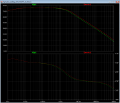
Great work, Jack! However I think it would be even better to use a newer MOSFET which incorporates the higher effective mobility and lower effective channel length improvements that the past 20 years of technology progress have produced. Maybe something like the IRF2805L (datasheet). I'm suggesting this particular MOSFET because its SPICE .MODEL is pre-supplied with LTSPICE.Here's a simulation bode plot of the SR with the MJD44H11 pass transistor and an IRFP240 mosfet pass device, AD825AR error amplifier:
When I simulate the Jung/Didden SuperRegulator with D44H11 BJT pass transistor (green trace) and again with the IRF2805S MOSFET pass transistor, I find that the MOSFET regulator's performance is slightly better than the BJTs. Results attached.
Best regards,
Mark Johnson
{sorry for the fontology screaming}
Attachments
Jack, do you mean series inserting it in the loop, or breaking the loop and then hanging the resistor from one of the breakage points to ground to act as a source? Sorry if I don't understand. 🙄 Thanks for your work and info, by the way!
I break the loop just by inserting a voltage source in series. Or I insert a 1GH inductor in series and a voltage source in series with a 1GC capacitor, not to disturb bias but pass AC. Are we saying the same thing?
I seem to get results that look like Mark's. 🙂
I break the loop just by inserting a voltage source in series. Or I insert a 1GH inductor in series and a voltage source in series with a 1GC capacitor, not to disturb bias but pass AC. Are we saying the same thing?
I seem to get results that look like Mark's. 🙂
D'oh! Why not put all three on the same graph? So here they are.
- Green trace = BJT (D44H11)
- Blue trace = old MOSFET (IRFP240) that Jack simulated
- Red trace = new MOSFET (IRF2805L) that I recommend
Attachments
Nice transistor -- IRF2805 -- had a little trouble getting the model to work:
An externally hosted image should be here but it was not working when we last tested it.
Those plots were of the original 1995 regulator -- the non-bootstrapped version. If you want to have fun with the plots, use the model for the AD797AN and play around with the ESR of the caps throughout the system.
If you want to have fun with the plots, ... play around with the ESR of the caps throughout the system.
No (badword) Sherlock! Just try to replicate Jack's results with the BJT pass device, particularly the phase response between 10kHz and 1MHz. You'll discover that there is one particular cap whose ESR completely dictates the stability margin, and ESR=0 doesn't match Jack's plots.
And then you might ask yourself: golly, this is extreme sensitivity; would I call that a design weakness?
And then you might ask yourself: golly, this is extreme sensitivity; would I call that a design weakness?
It's an issue if you try to use the AD797 -- but is a twitchy valve in a 1989 Testarossa a design flaw?
What is the difference in performance between this 2000 version, with BJT or MOSFET, and the 1995 version with the pre-regulator that has measured so well against the others in the recent Linear Audio review?
Can one of you helpful fellows point me to comparative graphs showing this?
Thanks very much. 🙂
Can one of you helpful fellows point me to comparative graphs showing this?
Thanks very much. 🙂
The 2000 "improved" regulator used a LM317/LM337 regulators as "pre-regulator" which meant that the "original" had less work to do. The "improved" version has slightly higher output impedance than the "original" and the error amplifier is run off the output. I think by the time the 2000 article was out, the towel had been thrown in on the AD797 -- it tested beautifully but stability was problematic.
What should the specifications of the LED be? The BOM just mentions the lead pitch.
Thanks
Mark.
Thanks
Mark.
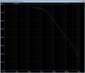
D'oh! Why not put all three on the same graph? So here they are.
Magnitude plot only, sorry. For phase, perform eyeball extrapolation on graphs in previous post.
- Green trace = BJT (D44H11)
- Blue trace = old MOSFET (IRFP240) that Jack simulated
- Red trace = new MOSFET (IRF2805L) that I recommend
That's quite interesting Mark! Wish I knew how good the various models really are. Maybe there's no way around actually measuring one.
Jan
What should the specifications of the LED be? The BOM just mentions the lead pitch.
Thanks
Mark.
I normally use a green LED because I have loads of them. I think any of the 2-3V LEDs are OK. There will be a variation in the current source but unless you want to push it up to 1A load I don't think it will matter.
Jan
Nice transistor -- IRF2805 -- had a little trouble getting the model to work
Indeed, quite high transconductance, very low Ron, etc. Good catch Mark, this may be a viable alternative for a BJT in high-current applications.
Maybe I should add a few to my next parts order. Farnell has them at $ 4 one off.
Jan
Here's a simulation bode plot of the SR with the MJD44H11 pass transistor and an IRFP240 mosfet pass device, AD825AR error amplifier
Jack how did you bias the opamp, did you put a zener in series with the opamp output?
Jan
Play with the infineon/NXP devices whose .MODELs are presupplied with LTSPICE; some of them perform still better in the Jung/Didden SuperRegulator. But since Jack and I can't get those in the USA 😡 , I mentioned the IR device instead. You may be able to get better MOSFETs, cheaper, purchasing from Netherlands.... this may be a viable alternative for a BJT in high-current applications.
Maybe I should add a few to my next parts order. Farnell has them at $ 4 one off.
Jan
Mouser has irf44rpbf at about 2 dollar each with .o28 ohm on and 15s forward trans min. driving it is only a little harder than irf240 with a magnitude of on res. lower . 60 volt rated . Just throwing out another pass transistor .Indeed, quite high transconductance, very low Ron, etc. Good catch Mark, this may be a viable alternative for a BJT in high-current applications.
Maybe I should add a few to my next parts order. Farnell has them at $ 4 one off.
Jan
I normally use a green LED because I have loads of them. I think any of the 2-3V LEDs are OK. There will be a variation in the current source but unless you want to push it up to 1A load I don't think it will matter.
Jan
Thanks, I think Ive sorted out my BOM now 😀
Newbee question for superreg.
Sorry to jump in with a basic question this far in the thread.. but I just discovered the thread today and wanted to implement the super reg as my first real DIY " newbee audio project" (with no magic smoke if possible😀)
I would like to replace my squeezebox touch PSU (1.5A) and the +5v on my CD Pro 2 Drive (1.5A)......
a. I have some AD797AN available..is a good choice for U1?
b...Also.... as I only require 2 +5 v PSUS can the negative side of the PCB be adapted for positive operation? (save buying 2 sets of PCBS?)
c... and..I also have to hand some BC550C but I don't think that's up to the pass transistor job is it?
Thanks for putting up with the questions this late on...I tried doing the math's by looking at the past threads but my results way off (I think?)
regards
Johnny
- It's possible to use the negative PS board, but you have to invert all polarized components on the board. Also you have to cut all the tracks to the opamp en swap input pins, and also voltage pins.
- For 1.5 amps output, most likely you have to tweak the current source (R1). Be careful not to overload the opamp. I've increased to current source from 4mA to 7.5mA to get 1A out with some margin. A larger heatsink could be necessary.
- For 1.5 amps output, most likely you have to tweak the current source (R1). Be careful not to overload the opamp. I've increased to current source from 4mA to 7.5mA to get 1A out with some margin. A larger heatsink could be necessary.
- Home
- The diyAudio Store
- Super Regulator