Looks alright but I have trouble following your math (could be me).
I would say (15-6.9)/6.9 = Rtop/Rbot.
Jan
I would say (15-6.9)/6.9 = Rtop/Rbot.
Jan
I started with this formula 6.9=(15*R7)/(R7+R6+R16) and solved for R6
There should only be 2 resistors involved, the feedback divider. What's R16?
Edit I see, yes you are right, that 100 ohms must be taken into account...
Jan
LATE TO THE GAME & FRUSTRATED IN PART SEARCH:
I wish to build the super regulator for the BA-3 as a line stage.
Are 512-BC5546BTF and 512-BC556BTF recommended by Per-Anders back in May of 2016 (#938) still the best substitutes for the now obsolete Q2 and Q4 transistors listed in Jan Didden's BOM?
And how do you choose heat sinks for Q1 and Q3? DigiKey and Mouser list thousands with parameters that are completely foreign to me! Any help will be much appreciated.
And how do you choose heat sinks for Q1 and Q3? DigiKey and Mouser list thousands with parameters that are completely foreign to me! Any help will be much appreciated.
If you mount the pass transistors from the bottom of the board, you can stab them to the bottom of your chassis and that should be sufficient to dissipate the heat. Make sure, of course, to use an insulating pad.
Are there any fully or partially integrated ICs that can perform as well as the super regulator?
If you want a plug-and-play solution the Silentswitcher, available from the diyaudio store, could be a good alternative.
Jan
Jan
I'm not looking for plug and play I'm looking to integrate similarly performing power supplies onto the variety of designs I have that doesn't take up so much space. I need a simplified solution that can be adapted to a variety of voltages that the silent switcher cannot give me.
Surely the super reg can't be the best the industry has come up with thus far? There must be a feedback IC I can strap to a pass device that can give similar performance?
Surely the super reg can't be the best the industry has come up with thus far? There must be a feedback IC I can strap to a pass device that can give similar performance?
Last edited:
Regs with that kind of performance don't grow on trees. There are more compact versions of the Didden reg but not available commercially, to my knowledge.
TPS7axxx based regs could be what you are looking for --> Google is your friend.
TPS7axxx based regs could be what you are looking for --> Google is your friend.
Yes TPS7A33xx and -47xx are probably what I would use for this. The problem may be that these are hard to solder if your workshop has limited capabilities...
Jan
Jan
I had my own PCB super reg made with the purpose of running 105v @ 2A.
It's essentially the same as the one sold here but with a darlington output a circuit to prevent the opamp from overvolting.
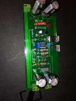
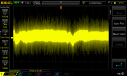
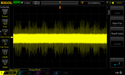
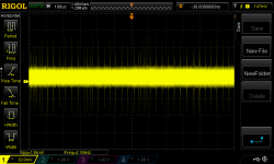
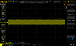
I ran the scope on it and received some confusing results.
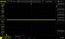
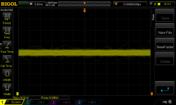
The top picture is of my 105v super reg.
The bottom picture is of the the 15v super reg sold here on the site.
On my version the scope shows no visual noise even at the max resolution of 5ns, it is so low the scope won't even register a frequency value. But it is showing a numerical value of 600mv of noise.
The 15v version is showing visual noise at 5ns but the numerical value is much lower at 30mv.
This is a confusing result. How can this be? What is true? Am I using the scope wrongly in some fundamental way?
It's essentially the same as the one sold here but with a darlington output a circuit to prevent the opamp from overvolting.

I ran the scope on it and received some confusing results.


The top picture is of my 105v super reg.
The bottom picture is of the the 15v super reg sold here on the site.
On my version the scope shows no visual noise even at the max resolution of 5ns, it is so low the scope won't even register a frequency value. But it is showing a numerical value of 600mv of noise.
The 15v version is showing visual noise at 5ns but the numerical value is much lower at 30mv.
This is a confusing result. How can this be? What is true? Am I using the scope wrongly in some fundamental way?
Last edited:
I had my own PCB super reg made with the purpose of running 105v @ 2A.
It's essentially the same as the one sold here but with a darlington output a circuit to prevent the opamp from overvolting.
View attachment 665664
I ran the scope on it and received some confusing results.
View attachment 665665
View attachment 665666
The top picture is of my 105v super reg.
The bottom picture is of the the 15v super reg sold here on the site.
On my version the scope shows no visual noise even at the max resolution of 5ns, it is so low the scope won't even register a frequency value. But it is showing a numerical value of 600mv of noise.
The 15v version is showing visual noise at 5ns but the numerical value is much lower at 30mv.
This is a confusing result. How can this be? What is true? Am I using the scope wrongly in some fundamental way?
Well in the top your vertical sens is 5V/div and 600mV seems realistic.
The bottom vert sens is 50mV/div. You're comparing two wildly different measurements.
BTW I appreciate you are rightly proud of your unit, but showing a schematic instead of a pic if you have a tech question is much more useful for those of us wanting to help ;-)
Jan
Last edited:
Last edited:
Why does the p-p voltage change with the time scale?
It doesn't. Look at the peaks, they really are the same. There's just not so many when you go to a faster timebase, and some of the higher ones are just missed.
The scope only 'sees' what is in the display window and when some of the highest are missed the lower ones are thought to 'be it'.
Jan
Last edited:
The measurement looks to be the same with the power supply off. Looks like background noise is screwing me here. At least that means the performance is probably where I want it to be, hopefully in the microvolt range.
Not sure how to get rid of the background oscillations though.
Not sure how to get rid of the background oscillations though.
Last edited:
Almost looks like some switching stuff. Any dimmers nearby? An SMPS-powered solder iron? What do you see when you short the scope probe to its ground clip?
BTW Nice schematic.
Jan
BTW Nice schematic.
Jan
I'm in the basement so not unless it's coming through the floor. Although the master breaker board for the house is 3 feet away from my bench...Almost looks like some switching stuff. Any dimmers nearby? An SMPS-powered solder iron?
About 12mv of noise. 50% less than I get when it is not shorted.What do you see when you short the scope probe to its ground clip?
Thanks, I made a mistake in the picture though, R11 and R12 is connected to the output of the reg, not at the input.BTW Nice schematic.
I probably want to put some darlington discharge resistors in to make it faster, I didn't know that was a thing until after I had the PCB made.
Plus I get some weird latch up issue sometimes when I turn it on and the output gets stuck @ 15v until I short the collector and emitter of Q5. I'm guessing this has something to do with the fact that the discharge resistors are not in place.
If there's any way you can think of to improve it let me know.
Last edited:
Which IC makes for a better super regulator replacement the TPS7A470 or the LT3045? Neither of these have impedance vs frequency plots on their datasheets so I can't tell. Can either of these truly replace a super regulator for regulation performance?
- Home
- The diyAudio Store
- Super Regulator
