Is it possible to replace both D2/7 and D5/10 with (only) two series of leds without any other alterations ?
D5/10 set the output voltage, together with the two feedback resistors.
D2/7 should be about half the output voltage.
I think that answers your question.
Jan
D2/7 should be about half the output voltage.
I think that answers your question.
Jan
No of cource not, that's 2 series of leds. Lets say 4 red (or maybe three green)
for D2/7 and the same for setup for D5/10. I have tried to find information if
it's possible to replace a voltage reference with leds but no definitive luck so far.
for D2/7 and the same for setup for D5/10. I have tried to find information if
it's possible to replace a voltage reference with leds but no definitive luck so far.
If you need something to offset the opamp output with about 7V, why would you use strings of LEDs?
I mean, sure, you can do that, but why?
And for the reference diode, the stock one is the '329 at some 6.9V, why replace that with LEDs, which will have worse impedance and can never get to exact 6.9V so you would need to fiddle with the feedback resistor ratio.
What is your rationale to attempt this? I'm genuinely interested.
Jan
Last edited:
Well, I did this and it seems that there are some people thinking that these two possitions could be done in different ways. Leds only was the first attempt.


I have 4 empty boards.
I'm reading this entire thread before ordering parts. (but only I'm up to page 40......)
Though, a quickie and somewhat vague question....
Do people use this as a "post SMPS" regulator ?
Is there any value by doing this ?
I'm reading this entire thread before ordering parts. (but only I'm up to page 40......)
Though, a quickie and somewhat vague question....
Do people use this as a "post SMPS" regulator ?
Is there any value by doing this ?
Haven't heard of anyone doing that, but first, what's the nature of the SMPS noise you are aiming to cure? Is it audible?Do people use this as a "post SMPS" regulator ?
Is there any value by doing this ?
That is the important question.what's the nature of the SMPS noise you are aiming to cure? Is it audible?
Right now I have no specific project for these boards....I'm examining my options.
But in the future, one use might be inside a (NOS) eurocard rack system that has a built-in SMPS psu.
I'll have test that SMPS ( +15v) for switching noise.
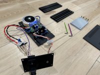
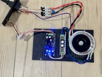
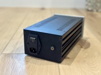
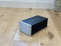
I don’t t see a lot of completed builds in this thread, so I thought I’d share some pics of mine. My goal was to build a 24vdc linear power supply for my diyaudio 6-24 crossover from the diyaudio store.
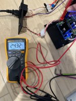
Using the “RESISTOR / VOLTAGE TABLE”, I used the 6.9 voltage reference with 2.4k R6 value to target 24.2 vdc actual output.
I got 24.3vdc so close enough?
Hooked it up to my system tonight and so far so good.
Thanks to Jan, contributors and @Gianluca for supplying the chassis (and catching my dwg mistake).
Attachments
-
 C32F1B21-9D65-4D3B-ABCE-5ADDEFA6B19A.jpeg525.7 KB · Views: 242
 -
 08FB7D89-F83E-4024-91C6-7E3DF5405DE4.jpeg371.6 KB · Views: 235
 -
 C5843F26-601D-46A5-B411-7B3F3290F37B.jpeg479.7 KB · Views: 220
 -
 A55352AD-18AF-4392-BC62-AF5092F6EEF6.jpeg236.1 KB · Views: 190
 -
 4EC7131D-9591-4318-AC41-077586BCC95C.jpeg247.8 KB · Views: 201

ASFAIK, you are the first to clearly show through photos, the correct way to wire this circuit. Others may make written descriptions or sketches, but an in focus close up photo is best in conjunction with the rest. Thanks for this.
Appreciate the feedback. There were many exploded capacitors and burned out LEDs preceding these pics, but I finally figured everything out.ASFAIK, you are the first to clearly show through photos, the correct way to wire this circuit. Others may make written descriptions or sketches, but an in focus close up photo is best in conjunction with the rest. Thanks for this.
I’ve built a couple amps (F6 and F5T) using this site and needed pics to help bridge the gap between understanding the schematics and a completed product.
Hopefully the ones I shared will do the same for others.
edwinjones4,
You hit it right on the head. I go to the vitamin store to buy a product, and the clerk says, "Oh yah, it's right there, next to the vitamin C".... Great. So I say, "come over here and touch it." I get various responses to this, and yes, I am careful with my tone of voice. You know what I would like to say. We all do it at times. The procedure is something that we have done many times before and so it is now second nature to us. Then when someone comes along for the first time and asks how, it can be forgotten how much we didn't know the first time.
You hit it right on the head. I go to the vitamin store to buy a product, and the clerk says, "Oh yah, it's right there, next to the vitamin C".... Great. So I say, "come over here and touch it." I get various responses to this, and yes, I am careful with my tone of voice. You know what I would like to say. We all do it at times. The procedure is something that we have done many times before and so it is now second nature to us. Then when someone comes along for the first time and asks how, it can be forgotten how much we didn't know the first time.
If I wanted to regulate a bipolar supply with these and was looking for minimal offset, is it good enough to closely match the setting resistors on positive and negative regulator, or do other aspects (parameters of the op amp, et. al.) play a role as well?
- Home
- The diyAudio Store
- Super Regulator