The problem with a 3.3V reg is that the opamp should also work reliably at 3.3V. The AD817 wouldn't; you need an opamp that can work lower.
There are not many, one is the ADA4099-1, but anyway not in DIL08 or SOIC08.
Jan
There are not many, one is the ADA4099-1, but anyway not in DIL08 or SOIC08.
Jan
MCP6021 has rail to rail outputs and inputs, works at 2.5V, 10MHz GBWP, 7 V/usec SR (datasheet)
Available in PDIP, SOT-23, SOIC-8, TSSOP-8, MSOP-8
_
Available in PDIP, SOT-23, SOIC-8, TSSOP-8, MSOP-8
_
That is a great find Mark, yes that should work well!
They even say they have a Spice model for it.
Jan
They even say they have a Spice model for it.
Jan
Thanks Jan for your help.
I'll leave it at 5V for now and then buy the 3.3V glass D power supply.
Dirk
I'll leave it at 5V for now and then buy the 3.3V glass D power supply.
Dirk
Thanks Jan,
Thanks Mark, I didn't see your post.
I ordered the MCP6021.
Is my calculation correct with the MCP6021.
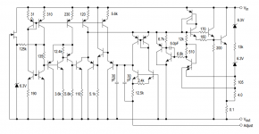
Dies ist der 5V-Regler.
AD518
D5 = LM4040AIZ 2,5 V.
R7 = 1K.
R6 = Brücke.
D2 = 2 rote LED. (3,2 V)
R5 = 4,99 K.
R2 = 10K.
3,3Volt with MCP6021.
3.3 volts - 3.2 V = 0.1 V.
0.1 / 3.2 = 0.03125
0.03125 x 1 K = 0.03125 KOhm ( 31,25 Ohm ) for R6
Dirk
Thanks Mark, I didn't see your post.
I ordered the MCP6021.
Is my calculation correct with the MCP6021.
Dies ist der 5V-Regler.
AD518
D5 = LM4040AIZ 2,5 V.
R7 = 1K.
R6 = Brücke.
D2 = 2 rote LED. (3,2 V)
R5 = 4,99 K.
R2 = 10K.
3,3Volt with MCP6021.
3.3 volts - 3.2 V = 0.1 V.
0.1 / 3.2 = 0.03125
0.03125 x 1 K = 0.03125 KOhm ( 31,25 Ohm ) for R6
Dirk
I built a 3.5V super reg using the AD8031 ( suggested by jan.didden) It works well and I used a Walter Jung GLED as the reference voltage. It does an admirable job to supply 3.3-3.5V to an ESS 9028Pro DAC as the AVCC. I also used the sense lines as well. I used 1n4148 as as a low voltage zener to center the op amp.
https://www.analog.com/media/en/technical-documentation/data-sheets/AD8031_8032.pdf
I am going to build another one using the LT6200, as I saw that op amp in one of Walter Jung's articles. I don't know if it will be stable and if it will sound better.
https://www.analog.com/media/en/technical-documentation/data-sheets/62001ff.pdf
Last edited:
Thanks Jan,
Thanks Mark, I didn't see your post.
I ordered the MCP6021.
Is my calculation correct with the MCP6021.
Dies ist der 5V-Regler.
AD518
D5 = LM4040AIZ 2,5 V.
R7 = 1K.
R6 = Brücke.
D2 = 2 rote LED. (3,2 V)
R5 = 4,99 K.
R2 = 10K.
3,3Volt with MCP6021.
3.3 volts - 3.2 V = 0.1 V.
0.1 / 3.2 = 0.03125
0.03125 x 1 K = 0.03125 KOhm ( 31,25 Ohm ) for R6
Dirk
Dirk if you include your schematic with your post, you have much more chance to get a reply.
Jan
I built a 3.5V super reg using the AD8031 ( suggested by jan.didden) It works well and I used a Walter Jung GLED as the reference voltage. It does an admirable job to supply 3.3-3.5V to an ESS 9028Pro DAC as the AVCC. I also used the sense lines as well. I used 1n4148 as as a low voltage zener to center the op amp.
https://www.analog.com/media/en/technical-documentation/data-sheets/AD8031_8032.pdf
I am going to build another one using the LT6200, as I saw that op amp in one of Walter Jung's articles. I don't know if it will be stable and if it will sound better.
https://www.analog.com/media/en/technical-documentation/data-sheets/62001ff.pdf
Forgot about that, yes, the AD8031 will also work well.
Jan
While I did get good results with the AD8031, WJ did not like it for its noise characteristics when I went over the GLED with him. Hence my future rebuild with the LT6200 but I fear instability. Won't know until it is tried. The AD8031 was mounted onto an adapter. The LT6200 will be directly soldered onto the board.
When I looked at the performance curves of the Super Reg, it looks like performance scales with higher performance but more finicky op amps.
When I looked at the performance curves of the Super Reg, it looks like performance scales with higher performance but more finicky op amps.
Two questions:
If there is 2.5V across R7, you need another 1.05V across R6 to get to 3.3V. I don't think 31.5 ohms will cut it. From the top of my head, 1.05V is almost half of 2.5V so I expect R6 to be almost half of R7, ballpark.
Secondly, the collector voltage of Q1 is 3.3V, it's base thus about 4V. Using two LEDs, the output of the opamp would need to be about 0.8V, close to zero. What is the logic behind that, why did you chose two LEDs?
Jan
So lets calculate R6. R7 is 1k and has 2.5V across it. According to Mr. Ohm, that's 2.5mA of current through it.
The same current flows throughR6 (the opamp input is very high impedance, no current into that).
So we're looking at an R6 value that gives 1.05V with 2.5mA.
According, again, to Mr. Ohm, V = I * R so R6 = V / I, 1.05/2.5 = 0.42. Since I is in mA, R must be in kohm, so R6 is 420 ohms. Easy-peasy.
We want the opamp output somewhere in the middle of the output voltage range, so a single LED will be fine.
Jan
Many thanks for your help,
@ 2LEDs, I had installed from the 5Volt version, changed 1 LED.
Regulator runs stable at 3.29 Volt.
Dirk.
@ 2LEDs, I had installed from the 5Volt version, changed 1 LED.
Regulator runs stable at 3.29 Volt.
Dirk.
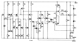
The transistor level circuit schematics of the Motorola and ST Microelectronics LM317 datasheets, look pretty complete to me. They match one another but Moto gives numerical values for the resistors.
Notice the typesetting error on the top left resistor value. It's 310 ohms but the zero has slid downwards a little bit! The other emitter degeneration resistor in the current mirror, tells you what you should be looking for.
_
Notice the typesetting error on the top left resistor value. It's 310 ohms but the zero has slid downwards a little bit! The other emitter degeneration resistor in the current mirror, tells you what you should be looking for.
_
Attachments
Thanks Mark, that's helpful.
BTW That dropping zero is common when your text window is too short. Typically happens to me in Powerpoint too ;-)
So I guess I have to bite the bullet and start entering this in LTspice. Not today though ;-)
Jan
BTW That dropping zero is common when your text window is too short. Typically happens to me in Powerpoint too ;-)
So I guess I have to bite the bullet and start entering this in LTspice. Not today though ;-)
Jan
Except for changing the output voltage and associated resistors what are the basic pros and cons of using the following in place of the LM329?
Is stability the issue? Or dynamic impedance?
Or would all of the above work ok? Or is PM329 & TL431 ok? But LED or Zener not such a great idea?
I ask since I have TL431, LEDs, Zeners and discrete transistors so I would like to choose the best of those on-hand options. Or if that is not a good idea I would like to understand why and then I will get the LM329. On one hand I would like to use the parts that I have on-hand but at the same time I don't want to degrade the performance for just one part.
- "PM329 Zener-Based 6.9V" from https://refsnregs.waltjung.org/2New_Vrefs_082715_Draft.pdf
- TL431
- String of LEDs like the two in the upper right of this PCB Low noise low impedance regulator based on Jung super regulator 4/TAA2000 ! | eBay
- A 6.8V Zener (or a 6.2V Zener with a series 1N4148)?
Is stability the issue? Or dynamic impedance?
Or would all of the above work ok? Or is PM329 & TL431 ok? But LED or Zener not such a great idea?
I ask since I have TL431, LEDs, Zeners and discrete transistors so I would like to choose the best of those on-hand options. Or if that is not a good idea I would like to understand why and then I will get the LM329. On one hand I would like to use the parts that I have on-hand but at the same time I don't want to degrade the performance for just one part.
Last edited:
I just read about the PM829: https://refsnregs.waltjung.org/The_PM829_Reference.pdf
Would that work as a direct substitute for the LM329 in the J-D Super Regulator without degrading anything? I have 6.2V 500mW Zeners. Not sure if they are Fairchild 1N5234B or another brand.
Noise is lower. I don't think DC stability is any concern here. (Right?) Anything else to consider when replacing the LM329 in the J-D Super Regulator?
Last edited:
- Home
- The diyAudio Store
- Super Regulator