"...only disadvantages." Check.
The best solution to a problem is not to create that problem in the first place.
The best solution to a problem is not to create that problem in the first place.
Yes that is exactly what they do, sense the output voltage remotely, so that the regulation takes place right at the load. That takes out the resistance and induction of the connecting wire.
The limitation is that the sense wiring itself has an induction and possibly a parasitic capacitance that can impact the regulator stability. That's why the RC is there on the sense line.
I haven't tested it on longer distances like placing it in a separate enclosure and running the wiring through an umbilical cable.
But, at any rate, there is absolutely no advantage in placing the regulator in a separate enclosure, only disadvantages.
Jan
makes a lot of sense, thanks!
Can I test the neg board by attaching a 19.5 v smps that I'm using at my bench with the pos lead to board "DCgnd" and ground lead to "-DCin'?
Can I test the neg board by attaching a 19.5 v smps that I'm using at my bench with the pos lead to board "DCgnd" and ground lead to "-DCin'?
Yes you can if you make sure there is no other ground connection to the SMPS.
BTW can you swap the opamp in the trouble regulator for another? It might be the opamp. If that makes no difference, can you replace the ' 329?
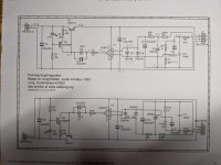
Edit: for you lurkers, what's the problem here in the pos reg? Voltages are penciled in. Expected Vo is 17 or 18V, but it's only 9.5 or so. What's wrong and why?
Jan
Attachments
Last edited:
OK, my lawyer tells me that posting this comment is not an admission of lurking...
I can't say anything about why but I have some observations on the voltages:
Shouldn't the input voltage be higher... on the order of 22-23V? How is 19.5V adequate?
Also the voltage at the top of D5 should be 6.9V with the LM329 not 4.07V, no?
Are the input/out voltages of the opamp equal enough at 3.51 and 3.45V?
And what should the voltage at the base of Q1 be? ~10v for a 10V diode (or was a 6.8V diode used?)
Good points.
I can't say anything about why but I have some observations on the voltages:
Shouldn't the input voltage be higher... on the order of 22-23V? How is 19.5V adequate?
Probably. But with a working reg you'd see the output go up until the limit of Vin, even if it wasn't enough.
Also the voltage at the top of D5 should be 6.9V with the LM329 not 4.07V, no?
Absolutely. What I don't understand is why not? Even with only 9V output.
Are the input/out voltages of the opamp equal enough at 3.51 and 3.45V?
The +input is higher so I would expect the output to slam as high as possible. Maybe the opamp is bad, that could also explain why there is only 4V across the b' 329, if the opamp inputs draw current.
And what should the voltage at the base of Q1 be? ~10v for a 10V diode (or was a 6.8V diode used?)
The zener? I think he used 6.8V which jives with the measurements.
Jan
Folks, is the part BC556BTF at digikey a suitable replacement for BC556BP asked for in the BOM to use for Q2?
Folks, is the part BC556BTF at digikey a suitable replacement for BC556BP asked for in the BOM to use for Q2?
Yes.
Your opamp isn't working.
I noticed that the AD825 supply is just a trifle below it's minimum. This could be a start-up issue because the input DC is too low for the required output. Test it with the original 24V input, it may be fine.
Jan
Jan
the bias resistor can be increased from 4.99k to 10k.
Of course the feedback resistors have to be recalculated for the new ration of 6.9V to 40V. So the resistor ratio should be 6.9 to (40-6.9)=33.1
2.2k and 10k would give a nominal 38.3V. Or 2.7k and 13k gives nominal 40.1V
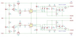
Thanks for all the work done here! I made a 40V output schematic very similar to the one shown in #1466 and tried to include your comments. Please have a brief look at attached screen shot and let me know if I have errors in it. Also is it safe to delete the protection diodes?
Attachments
Did you check the voltage rating of the pass transistors? I don't remember it off-hand.
You can delete the protection diodes, but why run the risk? They are very cheap.
Jan
You can delete the protection diodes, but why run the risk? They are very cheap.
Jan
Did you check the voltage rating of the pass transistors?
The data sheet says Vceo = 80Vdc, hope that's enough...?
You can delete the protection diodes, but why run the risk? They are very cheap.
OK, I will keep them, thanks!
Regulator is not stable without an output capacitor and min. load?Edit: for you lurkers, what's the problem here in the pos reg? Voltages are penciled in. Expected Vo is 17 or 18V, but it's only 9.5 or so. What's wrong and why?
Thanks for all the help, @Bill_P was right, it was the opamp. I went ahead and bought replacements for the diodes, and other transistors, just in case, as the major cost is the shipping from DigiKey. All is working well!
Question: For my final setup, I plan to use a 27-0-27 toroid I have on hand, however, I just tested it with my completed linear PS and I get 37V + - DC. Is this too high to put into the SuperRegulator (19V output). If I need to drop the voltage, can I just use a few 3W resistors on the output of the PS? If so, what values are suggested? I'm also willing to raise the superregulator output voltage, I can go up to 24V (powering BA2018 preamp).
Question: For my final setup, I plan to use a 27-0-27 toroid I have on hand, however, I just tested it with my completed linear PS and I get 37V + - DC. Is this too high to put into the SuperRegulator (19V output). If I need to drop the voltage, can I just use a few 3W resistors on the output of the PS? If so, what values are suggested? I'm also willing to raise the superregulator output voltage, I can go up to 24V (powering BA2018 preamp).
- Home
- The diyAudio Store
- Super Regulator