In response to Jan Didden's query on performance figures of Isources in post #428:
Here's a PSpice listing I ran this AM, which produces simulations of 4 Isource variations. In the plots, Vmon1 is the simple LED-based Isource, Vmon2 is Fred D's Isource with the LED driven from a JFET (I used the closest JFET model I had, the 2N5457),
Vmon3 is a 2N5457 JFET all by its lonesome, and Vmon4 is the FET/bipolar cascode described on here a few days ago.
Spice listing:
====================
LED_IS2 PNP Isource tests
*
* updated Wed 10-29-03 09:42:32
*
.OPT ACCT LIST NODE OPTS NOPAGE library
.WIDTH OUT=80
.DC VIN 10 25 0.1
.PROBE
.LIB D:\PS\PS61\LIB\JFET.LIB
.LIB D:\PS\PS61\LIB\BIPOLAR.LIB
.LIB D:\PS\PS61\LIB\DIODE.LIB
*
VIN 2 0 ; Vin is raw DC input
*
* ==== The simple Isource as per TAA article ===============
* (reference LED simulated as 1.6V source in series w/100 ohms)
*
R7 2 4 100 ; R7 emitter bias resistor
VLED 2 30 1.6
RLED 30 3 100
R5 3 0 10K ; LED bias r
* C B E
Q2 50 3 4 PN2907A ; Isource xistor
VMON1 50 0 0
*
* ==== FD Isource with JFET feed to reference ===============
*
R7B 2 41 100 ; R7 emitter bias resistor
VLEDB 2 300 1.6
RLEDB 31 300 100
JR5B 31 0 0 J2N5457 ; LED bias jfet
* C B E
Q2B 51 31 41 PN2907A ; Isource xistor
VMON2 51 0 0
*
* ==== A simple JFET Isource ===============
*
* D G S
J2 2 601 601 J2N5459
VMON3 601 0 0
*
* ==== A cascoded JFET Isource ===============
*
D3 501 2 D1N4736
R8 501 0 10K
Q3 500 501 60 PN2907A
* D G S
J1 2 60 60 J2N5459
VMON4 500 0 0
*
.end
=======================
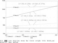
The plots show different levels of current, dependent upon the bias conditions. But what is important in comparison is the *slope* of the plots, which indicates the impedance of the source. The cascoded source is best, and shows a delta I of about 0.5uA for a 1V change in Vin. 4 cheap components to achieve this performance. Recommended for those who have the extra Vin, to provide working headroom.
wj
Here's a PSpice listing I ran this AM, which produces simulations of 4 Isource variations. In the plots, Vmon1 is the simple LED-based Isource, Vmon2 is Fred D's Isource with the LED driven from a JFET (I used the closest JFET model I had, the 2N5457),
Vmon3 is a 2N5457 JFET all by its lonesome, and Vmon4 is the FET/bipolar cascode described on here a few days ago.
Spice listing:
====================
LED_IS2 PNP Isource tests
*
* updated Wed 10-29-03 09:42:32
*
.OPT ACCT LIST NODE OPTS NOPAGE library
.WIDTH OUT=80
.DC VIN 10 25 0.1
.PROBE
.LIB D:\PS\PS61\LIB\JFET.LIB
.LIB D:\PS\PS61\LIB\BIPOLAR.LIB
.LIB D:\PS\PS61\LIB\DIODE.LIB
*
VIN 2 0 ; Vin is raw DC input
*
* ==== The simple Isource as per TAA article ===============
* (reference LED simulated as 1.6V source in series w/100 ohms)
*
R7 2 4 100 ; R7 emitter bias resistor
VLED 2 30 1.6
RLED 30 3 100
R5 3 0 10K ; LED bias r
* C B E
Q2 50 3 4 PN2907A ; Isource xistor
VMON1 50 0 0
*
* ==== FD Isource with JFET feed to reference ===============
*
R7B 2 41 100 ; R7 emitter bias resistor
VLEDB 2 300 1.6
RLEDB 31 300 100
JR5B 31 0 0 J2N5457 ; LED bias jfet
* C B E
Q2B 51 31 41 PN2907A ; Isource xistor
VMON2 51 0 0
*
* ==== A simple JFET Isource ===============
*
* D G S
J2 2 601 601 J2N5459
VMON3 601 0 0
*
* ==== A cascoded JFET Isource ===============
*
D3 501 2 D1N4736
R8 501 0 10K
Q3 500 501 60 PN2907A
* D G S
J1 2 60 60 J2N5459
VMON4 500 0 0
*
.end
=======================
The plots show different levels of current, dependent upon the bias conditions. But what is important in comparison is the *slope* of the plots, which indicates the impedance of the source. The cascoded source is best, and shows a delta I of about 0.5uA for a 1V change in Vin. 4 cheap components to achieve this performance. Recommended for those who have the extra Vin, to provide working headroom.
wj
Attachments
WaltJ said:In response to Jan Didden's query on performance figures of Isources in post #428:
Here's a PSpice listing I ran this AM, which produces simulations of 4 Isource variations. [snip]
wj
Thanks Walt, very instructive!
Jan Didden
> Wonder how close they measure to the predicted results. Some of us never trust predictions.........
You need a large supply of grains of salt to take with simulations.
The absolute accuracy may be dim. Walt's model-LED was 100Ω and someone above says 30Ω was measured. But of course real parts vary that much (series resistance is not a "critical parameter" in LEDs) so Walt's 100Ω value is "conservative".
But the general validity of stacking parts in SPICE is well proven. Walt's Vmon4 and Vmon2 are clearly better than Vmon1 or Vmon3. Vmon4 is 3,000 times better than Vmon1. Maybe in reality it is 1,000 times (or 10,000 times) better, and maybe it "doesn't need to be that good". But if you do find that the Vmon1 plan is a bit lame, the Vmon2 or Vmon4 plans are very good bets.
For people without math, here are Walt's simulated output impedances:
Vmon1 ==== 10KΩ
Vmon2 === 142KΩ
Vmon3 ==== 32KΩ
Vmon4 == 3,300KΩ
That last one begs for a frequency-sweep; you don't get 3MegΩ nodes at/above the top of the audio band. In simulation, you need a good-guess of stray capacitance (and a quick-check that model capacitances are about-right) to get a useful answer.
Last time that I measured the effective Z of a CCS thingie, it was at 1 kHz. If I get time to make any, I'll include data at 20 kHz, also.
Jocko
Jocko
LED impedance
at 0.4mA about 100 ohms
at 1.7 mA about 30 ohms
Since the impedance for a jfet current source decreases with increasing current
while LED impedance is also decreasing with increased Idss, I would imagine there is some current where the best power rejection is achieved with the lowest output conductance for the fet ( highest output impedance) and the lowest impedance for the LED. Maybe something on the low current end, like a J501 with a typical Idss of about 0.33 mA perhaps.........
Since Mr Jung itself is here, on the forum. Maybe we could get it's opinion on what the Jung Reg is good for and not.
I've read there that it's goof for loads >100mA; and for analogue "only"
But in the 04/95 article in TAA, Gary A. Galo uses them for DACs.
What's the designer's opinion? 😉
I've read there that it's goof for loads >100mA; and for analogue "only"
But in the 04/95 article in TAA, Gary A. Galo uses them for DACs.
What's the designer's opinion? 😉
This is getting VERY misleading.
Of course, we have a RATIO of 2 impedances that set the rejection. We have the effective impedance of the jfet, and the effective impedance of the LED.
Now think!
You can bust your tail to get the DC impedance of the jfet very high, BUT it will NOT hold with increasing frequency because of miller capacitance in the fet. The effective impedance will start falling off at 6dB/octave, sooner or later.
Now, the LED is a DIODE, so it changes its impedance directly with current. Therefore, increasing current through the LED will LOWER its impedance. The limit is the max operating current of the LED, and its intrinsic resistance, due to construction compromises. Usually, we would not usually bias the LED above about 5ma, and much below 1ma, as this will make the led noisy.
The j202, a popular and cheap device will work (barely), AND you don't even need an adjustable resistor, BECAUSE that would only force the LED to operate below 1ma, and that is bad for the LED.
Of course, we could use another part, like the j113, but why? First, it is a short gate, and has a more triode like characteristic than a long gate device like the j202, also it would HAVE to be adjusted to actually work. So why bother?
I hope that this helps.
> Since the impedance for a jfet current source decreases with increasing current while LED impedance is also decreasing with increased Idss, I would imagine there is some current where the best power rejection is achieved with the lowest output conductance for the fet (highest output impedance) and the lowest impedance for the LED.
Well, at a guess, I would suspect that the two effect are "parallel" for small changes of current, so changing the current will hardly change the rejection at all, certainly not enough to shout "Whoopee!".
Well, at a guess, I would suspect that the two effect are "parallel" for small changes of current, so changing the current will hardly change the rejection at all, certainly not enough to shout "Whoopee!".
Answering Bricolo's post #447...
They're good for both analog stages and also digital. With digital, the op amp gets a bit sticky, as a 5V part needs to be tailored for the use, and the ref. needs to be ~5V/2, i.e., 2.5V LM336 or equal. But it does work, and vastly improves things, in my experience(s). I've used AD817's for the 5V types, as well as the OP162 discussed in the ED 6/23/1997 article (ref. elsewhere in this thread). This latter article also uses one of those improved Isources.
wj
What's the designer's opinion?
They're good for both analog stages and also digital. With digital, the op amp gets a bit sticky, as a 5V part needs to be tailored for the use, and the ref. needs to be ~5V/2, i.e., 2.5V LM336 or equal. But it does work, and vastly improves things, in my experience(s). I've used AD817's for the 5V types, as well as the OP162 discussed in the ED 6/23/1997 article (ref. elsewhere in this thread). This latter article also uses one of those improved Isources.
wj
A supplement to post #437...
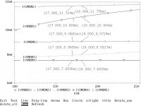
A spice file which uses 3 diodes as the "GREEN LED", and a real j202 JFET model for the FD Isource. Also, adds a simple Isource, VMON5, which uses AD589 1.2V ref. diode, offering alternate high performance.
Note: Diode dynamic Z for Isources VMON1 and VMON2 has been verified as ~100 ohms.
Note2: I still don't have a good model for a GREEN LED... if anyone has one, it would be interesting to try it here.
Note3: I referred to the "2N5457" in the text of the previous post (437). This was an error, as the actual part used was the 2N5459. The spice listing is correct.
===============
LED_IS3 PNP Isource tests
*
* updated Wed 10-29-03 15:02:33
*
.OPT ACCT LIST NODE OPTS NOPAGE library
.WIDTH OUT=80
.DC VIN 10 25 0.1
.PROBE
.LIB D:\PS\PS61\LIB\JFET.LIB
.LIB D:\PS\PS61\LIB\BIPOLAR.LIB
.LIB D:\PS\PS61\LIB\DIODE.LIB
*
VIN 2 0 ; Vin is raw DC input
*
* ==== The simple Isource as per TAA article ===============
* (reference GREEN LED is simulated as 3 1N4148s,
* dynamic Z is ~100 ohms at 10mA If)
*
R7 2 4 100 ; R7 emitter bias resistor
DLED1 2 1000 D1N4148
DLED2 1000 1001 D1N4148 ; LED hack of 3 series diodes
DLED3 1001 3 D1N4148
*VLED 2 30 1.6
*RLED 30 3 100
R5 3 0 10K ; LED bias r
* C B E
Q2 50 3 4 PN2907A ; Isource xistor
VMON1 50 0 0
*
* ==== FD Isource with J202 JFET feed to reference ===============
*
R7B 2 41 100 ; R7 emitter bias resistor
DLED1B 2 10000 D1N4148
DLED2B 10000 10001 D1N4148 ; LED hack of 3 series diodes
DLED3B 10001 31 D1N4148
*VLEDB 2 300 1.6
*RLEDB 31 300 100
JR5B 31 0 0 J202 ; LED bias jfet
* C B E
Q2B 51 31 41 PN2907A ; Isource xistor
VMON2 51 0 0
*
* ==== A simple JFET Isource ===============
*
* D G S
J2 2 601 601 J2N5459
VMON3 601 0 0
*
* ==== A cascoded JFET Isource ===============
*
D3 501 2 D1N4736
R8 501 0 10K
Q3 500 501 60 PN2907A
* D G S
J1 2 60 60 J2N5459
VMON4 500 0 0
*
* ==== A simple Isource as per ED 6/23/1997 article ===============
* (reference AD589 1.235V diode is simulated 1.235V source
* plus a 0.5 ohm series R)
*
R7C 2 40 50 ; R7 emitter bias resistor
VD1 2 2000 1.235 ; AD589 hack
RD1 2000 32 0.5 ; ""
R5C 32 0 33.2K ; diode bias r ==> ~0.5mA
* C B E
Q2C 2002 32 40 PN2907A ; Isource xistor
VMON5 2002 0 0
*
.end
=============================
Attachments
Straight from the source.
PRR,
Actually I looked the ratio trend it does appear start to increase rejection below a couple of mA. Mr. Curl is right (absolutely no surprise) about the about the noise starting to rise below about 1 mA. Even at third of a milliamp a green LED still appears to be far below the noise of most of the common inexpensive voltage references that one might use for voltage above a couple diode drops. Of course if one desires a precise voltage value that is stable with temperature there is no substitute for a good voltage reference.
http://www.analog.com/UploadedFiles/Technical_Articles/3752210Publication_V-Ref.pdf
Mr. Curl
I really don't see that any of this is really that misleading. I believe with your input on noise it would be probably desirable to shoot for a target of about a milliamp for the LED when biasing with a jfet current source. Right within the lower end of the Idss spread for the J202. Parts with Idss at the upper end of the spread can be adjusted down to 1 mA with a source resistor. Am I correct in understanding that this degeneration brings the output impedance up to the level of the
devices with Idss equal to 1 mA? I thank you for your as always, extremely valuable input. Maybe we managed to shine a little light on LED impedance and noise and also the characteristics of jfet current sources. A pretty good catch for one day of fishing in my opinion. For some data on jfet current sources:
J501 zip attached.
Thanks,
Fred
Fred, have you determined the 'breakpoint' where the effective capacitance of the fet starts to LOWER the effective impedance? I don't know where it is, but that must be taken into consideration. Why compromise the overall noise of the current source for a slightly improved 60Hz rejection, only for it to be compromised above about 1KHz or wherever it is?
For the record, GREEN LEDS are OK, but RED LED's would give you more 'headroom' if you needed it. This was my point. I often use green LED's myself, but then I usually have plenty of extra voltage at the input.
For the record, GREEN LEDS are OK, but RED LED's would give you more 'headroom' if you needed it. This was my point. I often use green LED's myself, but then I usually have plenty of extra voltage at the input.
Hi,
Personally, I stay away from LEDs and use JFETs instead...
Just my preference based on sonic results, that's all.
Cheers,😉
For the record, GREEN LEDS are OK, but RED LED's would give you more 'headroom' if you needed it. This was my point. I often use green LED's myself, but then I usually have plenty of extra voltage at the input.
Personally, I stay away from LEDs and use JFETs instead...
Just my preference based on sonic results, that's all.
Cheers,😉
> the 'breakpoint' where the effective capacitance of the fet starts to LOWER the effective impedance?
From the J500 CC-FET specs Fred posted (Thanks), taking 1mA as a likely trial value, the capacitance runs about 3pF and the dynamic resitance about 1Meg. Breakpoint is 53KHz, if my slip-stick isn't sticking in the heat (check me on that). Likely an octave or two lower on a real circuit board, if layout and cleanliness are not top-notch, so it could droop at the top of the audio band.
If we thought we needed more supply rejection, and do not care about practical details like existing circuit boards: use a 2K resistor and a 12V Zener to get a semi-constant reference 12V below the input voltage, then use the snazzy CC-FET and LED, 1N914-stack, or a 2-pin voltage reference diode fed from the 12V Zener. It's a pile of parts, but in DIY work the parts are less than the true value of the labor which is hopefully less than the value of the music enjoyment (don't lose sight of the goal when in the swamps of design).
The easy way
"From the J500 CC-FET specs Fred posted (Thanks), taking 1mA as a likely trial value, the capacitance runs about 3pF and the dynamic resitance about 1Meg. Breakpoint is 53KHz, if my slip-stick isn't sticking in the heat (check me on that). Likely an octave or two lower on a real circuit board, if layout and cleanliness are not top-notch, so it could droop at the top of the audio band. "
Why not just put a 0.01uF (or maybe larger but still with good RF characteristics) cap across the LED. You can kill some of the high frequency LED noise as well and still have a circuit that comes up quickly. If a cascode seems a little costly, a 5K to 6 K resistor could be used as degeneration with the gate referenced to the filtered voltage reference and the other end of the resistor to ground. It probably is required to bootstrap the voltage at the gate until the reference comes up after the regulator output comes up and biases the LM329. It could be a pretty simple and inexpensive circuit to do this though.
Attachments
Re: Thank you Fred!
That's Walt's gem. I just linked it
dimitri said:here is the gem
quote-----------------
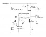
Electrolytic capacitors usually imply DC leakage errors, but the bootstrap connection of C1 causes its applied bias voltage to be only the relatively small drop across R2.
That's Walt's gem. I just linked it
Truly this could soon be considered absurd. Fred's last schematic is a wonderful thing, but the thoughtful designer must consider that this design cycle could tesselate infinitely. For example, the LM329 is biased with a resistor in Fred's last, but surely noise would be reduced if it was biased with a JFET current source! And on and on and on.
Also I'm having a hard time seeing how the LM329 could be considered less costly than the cascode. Last I ordered some, they were more than the $1.60 that caused so much ruckus upthread. I'm inclined to think the cascode would perform better, but that opinion isn't beyond single-digit stuff on the back of this envelope. For that matter I'm modelling this with BJTs instead of JFETs. Call me a heathen.
Also I'm having a hard time seeing how the LM329 could be considered less costly than the cascode. Last I ordered some, they were more than the $1.60 that caused so much ruckus upthread. I'm inclined to think the cascode would perform better, but that opinion isn't beyond single-digit stuff on the back of this envelope. For that matter I'm modelling this with BJTs instead of JFETs. Call me a heathen.
jwb said:
(...)Also I'm having a hard time seeing how the LM329 could be considered less costly than the cascode. Last I ordered some, they were more than the $1.60 that caused so much ruckus upthread.(...)
If I understand Fred's schematic correctly, the LM329 is doing double duty here. It's the reference for the current source, and also the main reference for the regulator itself. IOW, it was already there in its previous role, so there's no increase in cost from just giving it more jobs to do. After completion of startup, D2 is off, so the 329 is biased from the regulated output as it was before. But it gets a shot in the arm from D2 at startup.
- Home
- Amplifiers
- Power Supplies
- Super Regulator, collecting the facts