"3 pF => 53 kohms at 1 MOhms but don't forget stray capacitance also. I think it's equally important how the regulator performs in in the > 1 MHz range also unless your living room is a measurement chamber."
Very good. Your rejection into 100 ohm LED load has fallen to 54 dB at 1 megahertz assuming no capacitance across the LED. This is still an very good rejection number
at 1 MHz. I agree that very good rejection of RF makes for better sounding audio equipment.
Very good. Your rejection into 100 ohm LED load has fallen to 54 dB at 1 megahertz assuming no capacitance across the LED. This is still an very good rejection number
at 1 MHz. I agree that very good rejection of RF makes for better sounding audio equipment.
54 dB for the LED alone but what does it mean in total, at the output?Fred Dieckmann said:Very good. Your rejection into 100 ohm LED load has fallen to 54 dB at 1 megahertz assuming no capacitance across the LED. This is still an very good rejection number
at 1 MHz. I agree that very good rejection of RF makes for better sounding audio equipment.
Jan didden's post #387
I'll answer the comments above referencing also Fred D's sch. of the modified Isource, post # 390.
Yes, Jan, I can agree that this would work to some degree, and be both better and more simple (if not cheaper). I also agree with you that these JFET current regs. need lots of voltage to get beyond their knee, and flatten out to the highest Z. 4-5V maybe.
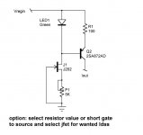
That said, they also may not be high enough in Z. I have found that a JFET cascode always works better for highest Z, albeit at the expense of even more voltage loss. Now we're up to 5-6V or more if another JFET is used as the cascoding device. But, given the high desirability of a cascode, modifying Fred's sch. further may be the very best alternative in terms of minimum component count, and also reasonable cost. Here's what to do with it:
1) Replace LED1 with a 6.8V zener, cathode to Vregin (dynamic Z will be a few ohms). This can be dropped down to 5.6V if headroom loss is a great worry.
2) Replace X2 with a 10k ohm resistor.
3) Replace Q2 with a PN2907A (lowest cost, lowest C part for the job, excellent Hfe).
4) Replace R1 with a 2N5459 JFET, selected for 4-5mA for the currents you describe. For lighter currents, a 2N5457 will suffice at around 2mA.
Most of the above parts are available from Digi-Key or Mouser for pocket change. High voltage parts can also be sub'd if desired for the 90V reg, with the 10k R adjusted upward in value.
This type of Isource has been tested both on the bench and via simulation, and the output Z is higher than that of the prior suggestion (which is limited by the non-cascoded xstr's sensitivity to Vcb variation).
A general point which should be understood about this type of regulator. With the inherent tight buffering of the op amp errors due to the rail bootstrapping, plus the reference diode being fed from the regulated output, the Isource errors constitute the major dynamic source of errors. Thus almost anything that can be done to improve Isource stability etc. is very much worthwhile (some might even read that to mean audible).
In other words, those posters asking about what the reg output does for various Isource topologies are on the right track. The answer is that it will change dynamically due to Isource imperfections, if you allow them to happen.
Now, after all that, maybe the prereg looks good?
wj
One change I have tried and also described in a post somewhere up north was the replacement of the entire input current source by a JFET current source. In other words, get rid of the LED, the PNP and related resistors and connect a FET CS directly from raw input (or after the prereg if implemented) to the pass transistor base. This improves the input ripple/noise rejection manyfold. But I found that a 1 or 2 mA CS was not enough to obtain good regulation above 100mA load or so. I had to look for a CS spec'ed at 5.6mA, that worked fine. As I noted earlier, these CS'es need some 5+ V across them so they ruin your dropout voltage. Still, it is an elegant and worthwhile mod if you have the extra input voltage. And it wouldn't need a PCB change I think.
I'll answer the comments above referencing also Fred D's sch. of the modified Isource, post # 390.
Yes, Jan, I can agree that this would work to some degree, and be both better and more simple (if not cheaper). I also agree with you that these JFET current regs. need lots of voltage to get beyond their knee, and flatten out to the highest Z. 4-5V maybe.
That said, they also may not be high enough in Z. I have found that a JFET cascode always works better for highest Z, albeit at the expense of even more voltage loss. Now we're up to 5-6V or more if another JFET is used as the cascoding device. But, given the high desirability of a cascode, modifying Fred's sch. further may be the very best alternative in terms of minimum component count, and also reasonable cost. Here's what to do with it:
1) Replace LED1 with a 6.8V zener, cathode to Vregin (dynamic Z will be a few ohms). This can be dropped down to 5.6V if headroom loss is a great worry.
2) Replace X2 with a 10k ohm resistor.
3) Replace Q2 with a PN2907A (lowest cost, lowest C part for the job, excellent Hfe).
4) Replace R1 with a 2N5459 JFET, selected for 4-5mA for the currents you describe. For lighter currents, a 2N5457 will suffice at around 2mA.
Most of the above parts are available from Digi-Key or Mouser for pocket change. High voltage parts can also be sub'd if desired for the 90V reg, with the 10k R adjusted upward in value.
This type of Isource has been tested both on the bench and via simulation, and the output Z is higher than that of the prior suggestion (which is limited by the non-cascoded xstr's sensitivity to Vcb variation).
A general point which should be understood about this type of regulator. With the inherent tight buffering of the op amp errors due to the rail bootstrapping, plus the reference diode being fed from the regulated output, the Isource errors constitute the major dynamic source of errors. Thus almost anything that can be done to improve Isource stability etc. is very much worthwhile (some might even read that to mean audible).
In other words, those posters asking about what the reg output does for various Isource topologies are on the right track. The answer is that it will change dynamically due to Isource imperfections, if you allow them to happen.
Now, after all that, maybe the prereg looks good?
wj
Replace Q2???
Not knowing which Q2 in which schematic, but..............
Do we really have to worry about saving 4 cents in a circuit that most likely has some high quality, and therefore, not cheap, film caps?
I bet Phred can find transistors with better h_fe linearity, and low capacitance, that don't cost $1 each.
With that $1 that they save, they can make their own current diode with a resistor and the right $0.40 JFET. And have enough left over to make a cascode version.
Unless, of course, there is no headroom. But this DIY, and I bet that they can find it if they want it bad enough.
Since this is DIY, I wonder how many guys trying to build a serious regulator are going to worry about a handful of inexpensive parts if it gives them another 10 dB or so of PSRR.
I bet most of them will do so, even with a pre-regulator. I would.....
Jocko
post #415
Just read the post, the sch. reference IS there.
FYI, a PN2907A costs a few pennies not $1.
Why *not* save the $, if one can have superior performance *and* low cost? The ckt. suggested does do that. The main expense is the loss of headroom, as cited.
Not knowing which Q2 in which schematic, but..............
Just read the post, the sch. reference IS there.
FYI, a PN2907A costs a few pennies not $1.
Why *not* save the $, if one can have superior performance *and* low cost? The ckt. suggested does do that. The main expense is the loss of headroom, as cited.
I just knew someone would object to Walt's "lowest cost".
> Not knowing which Q2 in which schematic
The top one.
> find transistors with better h_fe linearity, and low capacitance, that don't cost $1 each.
Hfe linearity is a non-issue: this device works constant-current. Hfe is important; but 2907 has enough Hfe that its base current will be swamped by the R-LED or Zener current. The exact value of Hfe is not critical: we only need to hold the source current higher than Darlington base current, and constant, not any exact amount.
Capacitance is critical, and mentioned by Walt: "PN2907A.. lowest cost, lowest C part...". The 2907 is a pretty-bitty die with small junctions and thus low capacitance. If you go comparing capacitance, be sure you compare at the working condition: Cob varies a lot with voltage and in some devices Cob varies somewhat with current. 2907 Hob at 30V is a mere 2pFd; you need a good layout so your layout strays don't degrade this.
I'd also place great weight on Walt's claim: "This type of Isource has been tested both on the bench and via simulation, and the output Z is higher than that of the prior suggestion...". He probably has a very-nice bench, and this kind of extreme application can't be "proven" with talk/theory or just simulation.
Or are you objecting to the HIGH cost of PN2907A? Yes, DigiKey asks a whopping $0.26 each, a big budget-buster. Their labor costs to sort parts into baggies must be high. But PN2907A is a good choice in many-many chores, so Super-Size your order: price is half if you buy 100 ($13). Or go to Mouser: $0.11 each, $6.00 for 100. Even cheaper if you do Suface-Mount and buy a reel (and you may be able to get parasitic capacitance down another pFd).
If you must pay more: 2N2907A comes in a TO-18 metal-can package for $0.60. I doubt it is better in any way that matters here, and may add a tenth-pFd stray capacitance off that metal can.
The 2907 is so cheap because it is a real sweet-spot for size, doping, gain, etc. Millions or billions have been made. And foundry costs are mostly up-front: the more you make the less they cost. Don't be put-off because it is 10 for a buck.
> Not knowing which Q2 in which schematic
The top one.
An externally hosted image should be here but it was not working when we last tested it.
> find transistors with better h_fe linearity, and low capacitance, that don't cost $1 each.
Hfe linearity is a non-issue: this device works constant-current. Hfe is important; but 2907 has enough Hfe that its base current will be swamped by the R-LED or Zener current. The exact value of Hfe is not critical: we only need to hold the source current higher than Darlington base current, and constant, not any exact amount.
Capacitance is critical, and mentioned by Walt: "PN2907A.. lowest cost, lowest C part...". The 2907 is a pretty-bitty die with small junctions and thus low capacitance. If you go comparing capacitance, be sure you compare at the working condition: Cob varies a lot with voltage and in some devices Cob varies somewhat with current. 2907 Hob at 30V is a mere 2pFd; you need a good layout so your layout strays don't degrade this.
I'd also place great weight on Walt's claim: "This type of Isource has been tested both on the bench and via simulation, and the output Z is higher than that of the prior suggestion...". He probably has a very-nice bench, and this kind of extreme application can't be "proven" with talk/theory or just simulation.
Or are you objecting to the HIGH cost of PN2907A? Yes, DigiKey asks a whopping $0.26 each, a big budget-buster. Their labor costs to sort parts into baggies must be high. But PN2907A is a good choice in many-many chores, so Super-Size your order: price is half if you buy 100 ($13). Or go to Mouser: $0.11 each, $6.00 for 100. Even cheaper if you do Suface-Mount and buy a reel (and you may be able to get parasitic capacitance down another pFd).
If you must pay more: 2N2907A comes in a TO-18 metal-can package for $0.60. I doubt it is better in any way that matters here, and may add a tenth-pFd stray capacitance off that metal can.
The 2907 is so cheap because it is a real sweet-spot for size, doping, gain, etc. Millions or billions have been made. And foundry costs are mostly up-front: the more you make the less they cost. Don't be put-off because it is 10 for a buck.
25 years ago, '2907s were all that we had.
That was 25 years ago.
As for the $1 jab, Walt was objecting to those current diodes, that cost >$1.
You can make a cascode version, to keep Walt happy with high Z, with 2 JFEts, and one resistor. <$1. Ooops.......too much space. Never mind.
Jocko
That was 25 years ago.
As for the $1 jab, Walt was objecting to those current diodes, that cost >$1.
You can make a cascode version, to keep Walt happy with high Z, with 2 JFEts, and one resistor. <$1. Ooops.......too much space. Never mind.
Jocko
post 418
I said *PN*2907A, not 2N2907. There is an important difference between the two. There is also the principle of "if it ain't broke don't fix it". And PRR has stated quite well the merits of the 2907 family.
All of this is certainly not to make *me* happy. I thought the purpose of this forum was to discuss various means of execution, and the pros/cons. Is it somehow lost on the readers here just how/why high-Z in this application is critical?
wj
25 years ago, '2907s were all that we had.
I said *PN*2907A, not 2N2907. There is an important difference between the two. There is also the principle of "if it ain't broke don't fix it". And PRR has stated quite well the merits of the 2907 family.
All of this is certainly not to make *me* happy. I thought the purpose of this forum was to discuss various means of execution, and the pros/cons. Is it somehow lost on the readers here just how/why high-Z in this application is critical?
wj
Running Amuk.........
I a little confused as to the interpetations people are taking from my idea.
All advocated was the replacement of the 10K resistor that biases the green LED. This LED serves as the reference voltage for the bipolar current source. There is no change in headroom since the 10K resistor sees the input voltage minus the 1.8V drop across the Green LED. There is plenty of voltage to operate a jfet or two terminal jfet current source in its linear and high inpedance region.
Walt is correct in stating the the J502 is fairly expensive and it is avalible for around $ 1.60 from Mouser. Another choice would be the the Vishay J202 at about 42 cents.
http://www.mouser.com/catalog/616/306.pdf
I am not suggesting not using a preregulator, but just a simple change from a resistor to a jfet to increase the PSRR of that portion of the regulator. It
is a very simple change that looks worthwhile to me. I will hold off on how to get rid of the level shifting circuit while still retaining the bootstrap supply
for the op amp (mod to ALW 14 volt regulator) by using a certain transistor
as the buffer between the op amp and pass transistor. I am afraid a riot would
break out.
Later,
Fred
We are also here to discuss various means of execution. We, well, mostly me, hasn't kept anyone happy for >50 years. We specialize in using the Pease mode of "show me where it says that it can't be done that way".
But anyway......the "PN" version still is only good for 40 V, as compared to a 2SA970, which is good for over twice that amount. Which implies that the '970 has a smaller base region, and most likely low capacitance.
The '970 has half the capacitance of the '2907, when measuerd at 10 V, and 1 MHz, as both are in their data sheets. And it is much more linear.
No, the high-Z aspect is not lost on all of us.
Jocko
Walt,
Thanks for the inputs (verbal/literary I mean...). I remember measuring the JFET source as aroung 150kOhms dynamic impedance, with the "normal" LED/xsistor source below 20k. I found that improvement worthwhile. But I'm sure the compound you describe would better that by some margin.
Jan Didden
Thanks for the inputs (verbal/literary I mean...). I remember measuring the JFET source as aroung 150kOhms dynamic impedance, with the "normal" LED/xsistor source below 20k. I found that improvement worthwhile. But I'm sure the compound you describe would better that by some margin.
Jan Didden
I think that you could change the green led to a red one and get lower effective voltage drop. Heck, you could use 1 diode instead of an led. Then a FET current source would be really more important. You should use current source fets if you can, and are not expert. They are already selected and optimized at the rated current. The Vishay j202 seems to be a pretty good deal, if it is like the j502 in performance.
Don't expect VERY high effective impedances with fets, unless they are long gate devices. This would be unusual with cheaper fets. Cascode is recommended in many cases.
Don't expect VERY high effective impedances with fets, unless they are long gate devices. This would be unusual with cheaper fets. Cascode is recommended in many cases.
Once again..........
The J202 is a regular jfet and not a two terminal jfet CCS. fairchild makes it as well.
http://www.datasheetcatalog.com/datasheet/J/J202.shtml
I suggested it for biasing the LED and using the bipolar transistor for the actual current source to the regulator. It will be very difficult to make a fet current source for ten mA and low drop out voltage.
Jfet current sources:
http://www.vishay.com/document/70596/70596.pdf
If you NEED a current source, the j202 on reflection is actually a poor choice for a current source, UNLESS you know how to sort for current or calibrate it with a series resistor. This is beyond most people here, and it takes a certain amount of time and a large number of parts. There are better parts with a lower Vgs, such as the 2SK170 Gr that would work OK, once selected out to the right current value of Idss.
Don't use a J202?
I thought that you said that you need a long gate device. According to Siliconix AN103, a J202 is such a device.
Yeah, I would use the '170 too, but only because I have a lot of them around.
Depending on the current range you are designing for, you can make a FET CCS with a dynamic Z > 1 Megohm.
I think we are generally in agreement, +/- a few tenths of a dB, in a manner of speaking.
Obviously not in terms of actual PSRR. (Hey, it is only a joke, guys......)
Jocko
Re: Don't use a J202?
Jocko, I don't have the type numbers I used in my head right now (it was on of the Jxxx series) but the ones that get close to 1MOhms are the ones with low current (1mA). They would be usefull for the LED current source. I just wanted one to replace the whole shebang, 5-6mA and that was much lower in impedance (150K IIRC).
Still, I would be interested to know if anyone has done some measurement on the actual impedance of the LED cum CS compound CS. Anyone has any figures?
jan Didden
Jocko Homo said:[snip]Depending on the current range you are designing for, you can make a FET CCS with a dynamic Z > 1 Megohm.
[snip]Jocko
Jocko, I don't have the type numbers I used in my head right now (it was on of the Jxxx series) but the ones that get close to 1MOhms are the ones with low current (1mA). They would be usefull for the LED current source. I just wanted one to replace the whole shebang, 5-6mA and that was much lower in impedance (150K IIRC).
Still, I would be interested to know if anyone has done some measurement on the actual impedance of the LED cum CS compound CS. Anyone has any figures?
jan Didden
Ok folks, we are talking in circles.
First of all: Do we just want to use a fet as a current source from the supply input? If we do, then we have to use a low Vp device. That means, high Gm. It will have marginal output impedance and it will amplify its own noise, but it can be made to work.
Or do we want to use a fet as a current source to bias a LED that is connected to the supply, while the fet current source is connected to ground? Then, a relatively high voltage 40-50V part, usually a long gate type, like the J202 is recommended, as it will allow relatively high voltage across it, and because it has low Gm, will not amplify its own noise as much. A current source fet will work as well, but they are fairly noisy, and relatively expensive. Their greatest advantage is that you know the current they will pass, because they are selected at the factory to have a specific current.
Effective impedances above 20K are practical with the fets discussed here, but only a cascode will get you there, for sure. Watch out for short gate devices (high Gm) They sometimes look like a triode, rather than a pentode.
I just checked a j232 and it has a very high output impedance, much higher that I suspected that it would have.
Conspiracy of complexity?
"If you NEED a current source, the j202 on reflection is actually a poor choice for a current source, UNLESS you know how to sort for current or calibrate it with a series resistor. This is beyond most people here, and it takes a certain amount of time and a large number of parts. There are better parts with a lower Vgs, such as the 2SK170 Gr that would work OK, once selected out to the right current value of Idss."
"Or do we want to use a fet as a current source to bias a LED that is connected to the supply, while the fet current source is connected to ground?"
YES, THAT'S WHAT I HAVE BEEN TALKING ABOUT ALL ALONG.......
Your just having fun with us now John...... The J202 was recommended as replacement for the 2N4340 mentioned in the Siliconix "The FET Constant Current Source" ap note. It has very a low output conductance of a few micro-mhos typical of those jfets that make good current sources and a drain to source capacitance of about one pF. It seems that jfets with large foward transcondutance like the 2SK170 don't make the best jfet current sources.
I agree that a two terminal current source would be better still, but I created a near panic by recommending one THAT COST A DOLLAR AND SIXTY CENTS! Putting a trim pot together with a jfet to dial in the current to the value desired is easy. It is not beyond any one here with a soldering iron, a VOM, and the initiative to read the article referred to above. In the context of biasing the LED in the BJT current source, the actual value of the current biasing the the LED is not that important. I would shoot for a value in the 0.5 to one mA range and not get anal about it in this particular circuit.
Once again, all of this was about biasing the LED for the bipolar constant current source and making the BJT current source more immune to voltage variations in the supply voltage. I believe it is worth doing whether one is using a preregulator or not, but obviously it's more important when not using a preregulator. Assuming an LED impedance of about 30 ohms (based on measurements) the change in LED voltage with input voltage is about 30/10000 or 3 mV per volt. One hundred ohms of emitter degeneration gives about 30 microamps per volt change for an output impedance of about 33.3 K ohms.
It appears to me that the bias current change the in the LED voltage reference is the dominant factor controlling the effective output impedance of the BJT current source under discussion. Replacing the 10 K resistor with a jfet current source with a 1 megohm impedance should give an improvement in output impedance of about 2 orders of magnitude, a pretty good return for the investment of one jfet.
As I recall the regulator article series was called "Regulators for High Performance Audio." By way of analogy, it seems to me that we are talking about building race cars and not about the most practical and economical car to drive to work and the grocery store.
Fred Dieckmann
PS I forgive you because I know you'll drop us another subtle but valuable circuit hint. I pay very close attention to both you and Mr. Pass when you throw those casual BTW pearls of wisdom out,
just to see if anyone notices. It seems that often, the more casual and low key it is, the more useful the information. I think you and Nelson have fun whispering the good stuff during all the shouting over the endless debates on usless topics. Don't worry the sensible members are watching very closely when you guys post the good stuff that we are here to learn in the first place.
Attachments
No one expects the jfet current source
My last post was before I saw Mr. Curl's last post and I hope he will forgive me for the "comfy chair inquisition".
J232......was it? One of those BTW goodies I was talking about.
Thanks John,
Fred
My last post was before I saw Mr. Curl's last post and I hope he will forgive me for the "comfy chair inquisition".
J232......was it? One of those BTW goodies I was talking about.
Thanks John,
Fred
Re: Jan didden's post #387
My wondering was about the fact the you have 1k+1k across the pass the transistor (for the LM317) and therefore make the inpedance of this transistors much less (=less PSSR?).
I think it's wonderful that Walt has turned this long thread back into the main track. It's wonderful to just talk about electronics and ventilate different ideas, crazy or not.
The prereg seem to be a good idea and very cost-effective also but how much does this circuit improve the PSRR of the whole regulator? Anyone who knows?WaltJ said:In other words, those posters asking about what the reg output does for various Isource topologies are on the right track. The answer is that it will change dynamically due to Isource imperfections, if you allow them to happen.
Now, after all that, maybe the prereg looks good?
My wondering was about the fact the you have 1k+1k across the pass the transistor (for the LM317) and therefore make the inpedance of this transistors much less (=less PSSR?).
I think it's wonderful that Walt has turned this long thread back into the main track. It's wonderful to just talk about electronics and ventilate different ideas, crazy or not.
- Home
- Amplifiers
- Power Supplies
- Super Regulator, collecting the facts