Hello my dear forum friends, how are you?
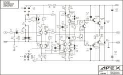
I assembled the SR100 amplifier and am using it on a -30/0/+30vdc source, I would like to know if it is safe to use the SR100 with a -45/0/+45vdc source at 4ohms, and if there is a need to add 4 resistors 2k2/2w instead of 1K/2w? as there are layouts with these two resistor values on the boards.
I assembled the SR100 amplifier and am using it on a -30/0/+30vdc source, I would like to know if it is safe to use the SR100 with a -45/0/+45vdc source at 4ohms, and if there is a need to add 4 resistors 2k2/2w instead of 1K/2w? as there are layouts with these two resistor values on the boards.
I really want to try this amplifier. Is the supply voltage +-75v? Can I use mje15030 and 15031 instead of 2sc4793 and 2sa1837?SRA 28
I have a similar question.I really want to try this amplifier. Is the supply voltage +-75v? Can I use mje15030 and 15031 instead of 2sc4793 and 2sa1837?
Which are the most important specs to match in a replacement for the 2SC4793/2SA1837?
VCBO Max 230V
VCBE Max 230V
VEBO 5V
fT 100mHz
Cob 20pF
I can find replacements that are the same in each of those respects but none is the same in all so which ones are most critical?
several years ago I have create the schematic for Linn's power amp modell "KLOUT" - go to the pdf file No 3-6 (post #51) under
http://www.diyaudio.com/forums/solid-state/106226-tweaking-classic-linn-lk1-lk2-lk280-6.html
maybe interesting ideas for various kind of protecting together with serial voltage regulation.
Hi, I can't find the Klout schematic.... I need to find it to repair my amplifier
Here are the schematics mentioned above. Not familiar with the Klout so unsure if I am posting everything.
Attachments
thank you very much, I hope they can help bring my Klout back to life and continue listening to my favorite music. I'll update you about it.Thanks so much again.
Sir Mile
Please suggest me High Frequency (crispy sound)full Range amp suggest upto75w to 100w at 4r and
150w to 200w at 4r
Thanks n Regards
Please suggest me High Frequency (crispy sound)full Range amp suggest upto75w to 100w at 4r and
150w to 200w at 4r
Thanks n Regards
Hi. I built an apex sr 100 with two pairs of transistors, perfect sound. worth a try. many thanks to Mr. Mile
Please ReplySir Mile
Please suggest me High Frequency (crispy sound)full Range amp suggest upto75w to 100w at 4r and
150w to 200w at 4r
Thanks n Regards
Hi everyone, although I'm not an expert, I'm trying to repair my Klout. On a control board (PCAS 161) I replaced a ceramic capacitor (C11) but I saw that the resistor R23 also burned out. The code for this one is 6:5 but I can't identify it and therefore I can't find it from retailers. The intact one measures approximately 5Mohm. The strange thing is that if the positive tip of the tester is placed on side 6 it gives the value of 5 Mohm, if placed on side 5 it gives 6.9Mohm. Does anyone know this type of resistor and where can I buy it?

newest attempt of SR300 pcb,added APEX controle(power-signal-clip) and APEX-protect to the board. i tried to draw as short as i could all small signal traces and also tried to avoid electro-magnetic circle made with copper traces with large currents,that is why i used three PGND places on a pcb. all of those large current traces (as i could see) are as short as possible,and do not share any current from other (positive/negative) side across the PCB,and they are placed shortly up to the right/left upper side of PCB pretty much away from input stage. all grounds from input stage have met together at one point-at one end of 10r resistor (no sharing currents) whose other end is connected directly to the GND of PSU. i avoid to put Zobel inductor on an amplifier PCB or any inductor if possible,so there is aditional small pcb wich contains protect relay anz Zobel R-L and R-C so one can use it together or wich ever is prefering.
it is not been checked out yet but it is a work in progress...
(untill it is not checked in practice i will not post any other files)
Hi 44250,
Which is the Most Stable And Tested version of This Amp. SR200 rev 3.1 or SR300
Wow! 171 pages!
Is there anywhere within this thread with test results showing that this amp would be a true reference?
Is there anywhere within this thread with test results showing that this amp would be a true reference?
In place or unsoldered ?The strange thing is that if the positive tip of the tester is placed on side 6 it gives the value of 5 Mohm, if placed on side 5 it gives 6.9Mohm. Does anyone know this type of resistor and where can I buy it?
in place... the resistor R23 in place measures a very low value but after desoldering it its measurement is normal i.e. 6.8 M ohm on both sides. I fixed the resistance again and everything went back to normal. I don't know why... maybe a false contact
Mr. Sunny22G, how do you solve the shock problem?Finally My SR200 is perfectly working. Lf411 is available in my area so I use TL071. But with TL071 .400 mv DC on speaker out terminal. Now I change TL071 with AD711, now DC is 000 on speaker out terminal. Now my sr200 sounds superb.I think my tl071 fake or may be its gain too high for this amp.
Thanks Mr. Miles for this such good amplifier and Thanks for other Diy members who very helpful for save my Dream.
I have Question can I add one more pair in this amplifier.
Regards
Sunny
- Home
- Amplifiers
- Solid State
- Studio Reference Amplifier
