Good day, please tell me what kind of quiescent current is needed for the apex sr 200 amplifier?
Hello Dragan and everyone. Thank you very much for your support. I measured -16 VDC on capacitor C8.
The Christmas holidays are about to start, so I'll check it out later. When I get to it, I'll write what I measured. I wish you a merry Christmas.
If C8 has on one side voltage measurement to GND some -16V
then you must have several Output Offset, approx. -15V.
Maybe you measure voltage on C6, there -16V is OK!
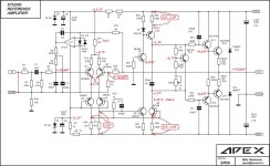
I draw in SR schematic typical node voltages, and also some voltage drops on resistors (see VAS section)
To do properly debugging, we need your amp voltage measurements to proceed forward!
Attachments
Good day, please tell me what kind of quiescent current is needed for the apex sr 200 amplifier?
50mA per output pair is sufficient.
If your heat sink can stand more, more quiescent current is better for lowering THD, but with higher temp dissipation at rest.
But dont exaggerate....the benefits in higher output bias/quiescent current til 150mA/out_pair is OK!

Hi Mr. Dragan. Thank you very much for the documents. When I have time, I will measure and document everything. I also looked at your resistance recommendation and it is indeed 220 Ohms.
Hello, today I took the measurements and wrote them in the diagram. Some measurements are different. The DC component at the output with the op amp is 0 VDC. When I pull out the LF411 operational amplifier, the output is 1.5 VDC. I have +18.8 VDC to ground on the collector of Q10 and 0 VDC to the collector of Q6. Please follow the next procedure for repair.If C8 has on one side voltage measurement to GND some -16V
then you must have several Output Offset, approx. -15V.
Maybe you measure voltage on C6, there -16V is OK!
I draw in SR schematic typical node voltages, and also some voltage drops on resistors (see VAS section)
To do properly debugging, we need your amp voltage measurements to proceed forward!
Attachments
OK
I need only measurements with OP DCservo ON (LF411 ON)
it will be much easier to deb-uging
I need only measurements with OP DCservo ON (LF411 ON)
it will be much easier to deb-uging
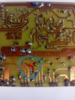
Hi Dragan, thank you very much for your interest and background. Everything was measured with an operational amplifier. I just tried it without and the protection with NE555 started, then I measured the DC on the 1.5V output. What else should I check?
Circled are my measured values.Hello, today I took the measurements and wrote them in the diagram. Some measurements are different. The DC component at the output with the op amp is 0 VDC. When I pull out the LF411 operational amplifier, the output is 1.5 VDC. I have +18.8 VDC to ground on the collector of Q10 and 0 VDC to the collector of Q6. Please follow the next procedure for repair.
Attachments

Obviouslly yours D1, D2 zeners are 18V type, but this is steel OK!
DCservo is working properly, you measurements on base Q1 is 14mV with 0,0mV OUTput voltage.
Your VAS current is aprox 13,3mA, A little to mutch...
Q10 , Q7, Q5 and Q6 are working with @ 42..43VDC PSU with Ptot/BJT => 0,55W/bjt, ...are they HOT? 60°C+++?
Q10 collector measurement of +18,8V is abnormal!
How do you measure C8 voltage 2,35V, with collector Q10 of +18,8V and collector of Q6 0,01V (you write those differ. in 2,35V???)
Q11 with Vbe_Q11 of 0,85V is NOT what do we aspect (0,55....0,65V)
Please measure additional:
Base to OUT : Q14 and Q13
and Base to OUT: Q12 and Q15
deltaU_R33 220R must be aprox 2xVbe => 1,2...1,4V (2xVbe) and no that measurement of 0,89V => only 1xVbe
something in Q12, Q13, Q14, Q15 is NOT GOOD at all!
Fake?
Last edited:
In case your VAS BJTs are too hot (Q10 , Q7, Q5 and Q6), it is necessary to reduce the IPS CCS (your 18V D2 with R11 15K => 1.8mA)
VAS CCS is now approx. 13.3mA, which is definitely too much.
If you would like to reduce this VAS CCS a bit, then it is easier to do it by increasing R11 to 18K.
VAS CCS is now approx. 13.3mA, which is definitely too much.
If you would like to reduce this VAS CCS a bit, then it is easier to do it by increasing R11 to 18K.
If I have time, I will do another measurement. I will check again the things you wrote Dragan100.
Thank you and Happy New Year to everyone at Diy audio.
Thank you and Happy New Year to everyone at Diy audio.
Hi mira1,
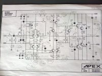
I would ask you to write down the new measurement values into a clean schematic,
because that way we will be sure "what belongs where!" Use MS Paint. like I do in one of my previous ones posts!
Leave DCservo opamp in circuit!
The +18.8V (to GND) measurement on the Q10 collector with 0,0V at collector Q6 is interesting:
U_C8 = 18,8V = (4x Vbe) + I_base*(R31+R32) + Ibias*(R34+R35)
so if two currents I_base and I_bias are 35..36mA the U_loop =>0, but this is not in your case!
But you have NO I_bias reading (voltage drop) on R34 or R35
and your voltage reading on R33 (220R) is 0,89V => cca 4mA
So the calculus for R31 and R32 must be approx.
(R31+R32)=(U_C8 - U_R33 - 2xVbe) / (I_R33) = (18,8 - 0,89)V / 4mA = 4K15
Probably you put 2x 2K2 instead of 220R for R31 and R32! Check down!
If you must change those resistors for smaller one (220R),
you can put there smaller values for R31/32 BaseStoppers, use some 47R....220R,
even R33 220R can be 100R, with more Aclass Drivers bias (12...15mA) => lower THD
BUT FIRST ADJUST trimmer P1 AT MAX ->1K, so you can start adjusting I_bias with MINIMUM current at next PowerON!
Then gradually increase I_bias so the voltage drop readings on R34 or R35 (0R33) are approx. 20...25mV
Also you can change R11 15K to 18K, your zeners in IPS are 18V, so the VAS bias is a little bit to "heavy" with them => 13,3mA
I_VAS <10mA is quite sufficient!
Last edited:
Hi Dragan100. Today I will take the measurements as you write. Thank you very much for your support and detailed explanation of where to measure what and how to calculate.
Znovu jsem tedy zkontroloval odpory R31, 32, 33, pro jistotu jsem je proletěl, jsou správné, vše jsem změřil. Znovu jsem prošel rozložení a zjistil, že R30, R31 a kolektor Q11 nejsou zapojeny. S největší pravděpodobností to bude příčina problému s nastavením. Možný?

Moderation edit:
Moderation edit:
So I checked resistors R31, 32, 33 again, flew through them just to be sure, they are correct, I measured everything. I went through the layout again and found that R30, R31 and the Q11 collector were not connected. Most likely, this will be the cause of the setup problem. Possible?
Attachments
Last edited by a moderator:
Zde je moje verze. Při pohledu na schéma se zdá, že došlo k chybě. Mám odkazovat, jak jsem dal ten červený? nebo se mýlím?
Moderation edit.
Moderation edit.
Here's my version. Looking at the diagram, it seems that an error has occurred. Should I refer to how I put the red one? Or am I wrong?
Attachments

Last edited by a moderator:
I am sorry. Again in English. I realized I listed a different version than I have. In my opinion, resistor R 30, R31 and collector Q11 are not connected on the PCB, as it is in the diagram. I have shown a possible error in the circle. Please is this reasoning correct? Thank you.
Attachments
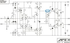
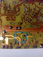

In the last picture I have shown in red where the connection should be. Please write if it is correct or if I am wrong.
- Home
- Amplifiers
- Solid State
- Studio Reference Amplifier