one can also make a mistake when drawing a schematic into diptrace. there is no 100% sure way to draw a pcb except testing it after sprint and diptrace.
If the schematic is correct in Diptrace, then the layout will be correct 100%.
Diptrace keeps the layout bound to the schematic.
You can also make a change in schematic and then automatically reflect it in the layout. You can automatically check the layout against the schematic as well as against the design rules that you define.
Same with eagle. its easy to make correct schematic, (but very difficult to make correct layout without schematic compatibility).
if schematic file already present as jpeg/bmp/png, I import it on a different layer then draw the schematic on top of it.
then ofcourse there are ERC (Electrical Rule Check in schematic) which checks missing connections , missing values, pin overlap, overlapping nets, and host of other checks.
once there are no ERC errors, as a final step, I go about checking each device's gender, pinout and orientation (which again is very easy in a schematic).
Hello Prasi,
Your methods are hierarchic. We designed like that back in the <80's. They require too much checking and are very time consuming. It is so easy to make a mistake. You have no layout DRC checking other than by eye, let alone it is an open ended process with no synchronization between schematic and layout.
Why perpetuate an error prone process when there are much better and free solutions available, i.e CadKey? Yes it is a learning curve, but well worth it in the end.
With Eagle you make pcb from the netlist in the schematic, therefore there can not be errors, and it has both ERC and DRC.
Some people adjust published pcb according to their needs, even with eagle: without schematic/netlist.
Hello Prasi,
Your methods are hierarchic. We designed like that back in the <80's. They require too much checking and are very time consuming. It is so easy to make a mistake. You have no layout DRC checking other than by eye, let alone it is an open ended process with no synchronization between schematic and layout.
Why perpetuate an error prone process when there are much better and free solutions available, i.e CadKey? Yes it is a learning curve, but well worth it in the end.
😕 I was speaking in favour of schematic compatibility softwares like eagle, diptrace, etc, I use eagle. I was detailing its features. Even in eagle schemaic its sometimes possible to insert a BCE device when you actually need a ECB. That's why I make it a point to check device pinouts/orientations even after schematic ERC is perfect.
And was saying that Its easier to make a correct schematic (and hence correct layout) than make a correct layout without the schematic compatibility inbuilt in the CAD.
I am not advocating/practicing error prone process.
Last edited:
Same with eagle. its easy to make correct schematic, (but very difficult to make correct layout without schematic compatibility).
if schematic file already present as jpeg/bmp/png, I import it on a different layer then draw the schematic on top of it.
then ofcourse there are ERC (Electrical Rule Check in schematic) which checks missing connections , missing values, pin overlap, overlapping nets, and host of other checks.
once there are no ERC errors, as a final step, I go about checking each device's gender, pinout and orientation (which again is very easy in a schematic).
Thank you prasi for this nice easy way !
Even in eagle schemaic its sometimes possible to insert a BCE device when you actually need a ECB. That's why I make it a point to check device pinouts/orientations even after schematic ERC is perfect.
The problem is that in different small signal transistor libraries, even the same transistor type can be found with different pinout. So, before using transistor, one should check the pinout for that particular component and compare it with the actual component. But common small signal transistors types are the only components where I found this inconsistency.
Sunny make sure that this transistor leds are not touching the power rails 😱 uyyyy! dangerous
its not touch. its space 2 mm
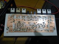
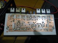
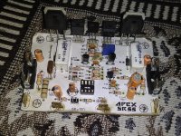
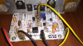
Apex SR55
Finally SR55 complete, its working fine, sound very nice, every tone very clear. Operating volt +/-40v DC, bias 8.5mv, but DC little high from my expectation 20-30mv. is it ok?. Thanks Prasi, Gannaji help me on this PCB and special thanks Mr. Mile for this Amplifier.
Regard
Gurpreet
Finally SR55 complete, its working fine, sound very nice, every tone very clear. Operating volt +/-40v DC, bias 8.5mv, but DC little high from my expectation 20-30mv. is it ok?. Thanks Prasi, Gannaji help me on this PCB and special thanks Mr. Mile for this Amplifier.
Regard
Gurpreet
Attachments
hi, to all experts here i want to ask if it is posible to use non-darlington pairs for SR20 like c5198,a1941 or TIP122,127 because i have those at hand and it was no use. my plan was to make an amp for my little 5" altec sub speaker and use it as full range to be used for my desktop
thanks
thanks
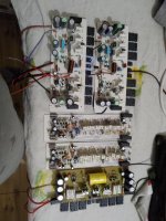
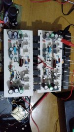
For those not aware of the sr200, why so many boards?
It's my favorite amplifire.
For those not aware of the sr200, why so many boards?
He built 5 channels of the same amplifier.
- Home
- Amplifiers
- Solid State
- Studio Reference Amplifier