Could you share it in PDF format for toner transfer.DC protect with blinking led indication.
Sir I total give up . All diy member plz tell me I want try 1 more time or not .sir mile if u read plz. Reply
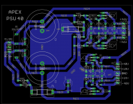
Hi. Psu40 is good for this? I accept any criticism.
Something is wrong .
I don't see CT connected.
Greetings brother.
I just checking .No 1 reply my massage. All day members ignore me included mile sir .I always respect all diy member.see my all post I always write Sir .Buy I ask many tiny my problem not 1 can help. Only u help me lot. .I have not this instrument .I have only dmm .I used good capacitor in PSU .I use 4 15000 uf in psu ..
Did you put them in the right way? is + on positive voltage and - on negative?

Sunny22, Try your amp at lower rail voltages of say +- 20v and test for stability.
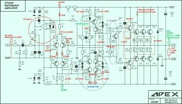
This way you won't lose output transistors when it malfunctions. I suspect the VAS stage compensation capacitor should be larger 33pf to 68pf.
If you are popping capacitors you have some sort of over-voltage situation occuring. This is also easier to measure at lower rail voltages for testing.
This way you won't lose output transistors when it malfunctions. I suspect the VAS stage compensation capacitor should be larger 33pf to 68pf.
If you are popping capacitors you have some sort of over-voltage situation occuring. This is also easier to measure at lower rail voltages for testing.
Sunny22, Try your amp at lower rail voltages of say +- 20v and test for stability.
This way you won't lose output transistors when it malfunctions. I suspect the VAS stage compensation capacitor should be larger 33pf to 68pf.
If you are popping capacitors you have some sort of over-voltage situation occuring. This is also easier to measure at lower rail voltages for testing.
I will make 4th time
I cannot got bc550 bc560 .I have bc547 bc557 b version .Is that really resion for less bass
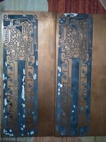
Can you show the picture of the popped capacitor?
I cannot got bc550 bc560 .I have bc547 bc557 b version .Is that really resion for less bass
No, that's not the reason.
You have mentioned some popped capacitors earlier. What are they (ref numbers)? Can we see the pictures of the damage?
Some signal generator would help a lot in your case - you can build a simple one yourself.
Otherwise, troubleshooting is rather difficult - lack of information.
Now I use 470uf if 63 volt. .Now try 5th time .sr200
Attachments
Now I use 470uf if 63 volt. .Now try 5th time .sr200
hi there if you make another module because you did not succeed on previous projects. then that is not the solution of your problem. you have work it out to make it work as i have said, people here are willing to help but they are not a clairvoyant. means you have to follow their suggestions.
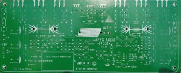
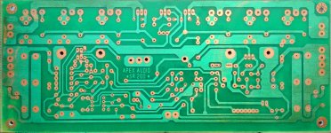
you have to take a clear resolution pictures for TOP and BOTTOM and voltage measurements so people can help you.
hi there if you make another module because you did not succeed on previous projects. then that is not the solution of your problem. you have work it out to make it work as i have said, people here are willing to help but they are not a clairvoyant. means you have to follow their suggestions.
you have to take a clear resolution pictures for TOP and BOTTOM and voltage measurements so people can help you.
OK sir
OK sir
courtesy of sir dragan
Attachments
Attachments
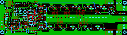
that's no problem they're the same just more output maximum number for SR200, that was Sonal's Layout. you can still read voltages on suggested tests points and compare the voltage measurements.
i suggest you ALWAYS check/verify any layout against schematic.
That capacitor is pp12
That's ok - my idea was to see what you mean by "popped capacitor" looking at its photo. Please give more information when you describe the problem.
There are only two reasons for the capacitor to pop - overvoltage and wrong polarity. Which one took place in your case?
Lack of bass is very subjective. Pretty easy to diagnose making a few measurements with the signal generator in place. Otherwise, we can only guess. In case the PSU provides the steady rails, powerful enough, the only part limiting the bass is the input filter C1, R3. What type of capacitor do you use for C1?
- Home
- Amplifiers
- Solid State
- Studio Reference Amplifier