Look here. Studio Reference Amplifier
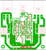
You can see the as build schematic.
If you prefer keep the servo and delete the two 470uf in series capacitors on the feedback circuit.
You can see the as build schematic.
If you prefer keep the servo and delete the two 470uf in series capacitors on the feedback circuit.
Last edited:
Hello bro thanks for helping. U are asking volt across resistor.
V(R25) =1.5volt
V(R26) =1.5 volt
V(R27) =1.5 volt
V(R28) =1.5volt
R33 1.2 volt
C22 2.4 volt
V(R25) =1.5volt
V(R26) =1.5 volt
V(R27) =1.5 volt
V(R28) =1.5volt
R33 1.2 volt
C22 2.4 volt
OK, what we see looking at those voltages:
Current through 100R resistors is 15mA
Current through 47K resistors is 1.1mA
That gives us the VAS current = 13.9mA
Way too much in my opinion. Q7, Q8, Q9 are expected to be very warm.
Correct VAS current is set by the value of R11 (the higher the value of R11 -> the lower the VAS current). Too high VAS current can reduce the stability margins.
If you increase the value of R11 up to 15K, you will need to re-adjust the bias.
All the rest looks good, if assembled correctly.
Sr200
Greetings .my ac is 45-0-45 8 amp transformer.dc output 63-0-63.15000uf*4 capacitor 60'000 rail
Greetings .my ac is 45-0-45 8 amp transformer.dc output 63-0-63.15000uf*4 capacitor 60'000 rail
hey Sunny with all respect you know the resistor color code well right? you think you might swith over a value by mistake? this do happen
Hello sir Q7 8 9 is cool not warm.
Hi Sunny, Q7, Q8, Q9 transistors are located on the local heatsinks. With +/-63V DC rails, each of them dissipates roughly 60V * 13.9mA = 834mW, which is pretty a lot for TO-126 package. If they are cool - something is wrong.
Are R20-R23 resistors really 47K (no mistake)?
The other question - did you manage to set the right idle current for the output transistors? Do you measure 23.5mV across 0.33R resistors?
Hello guys I'm gonna leave a Apex SR200 so you guys can use it to help Sunny I check it many time but I think one of you have more knowledge than me to help troblelshooting Sunny's build
Hi Juan, thank you for the sim file - it will help for sure.

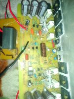
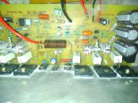
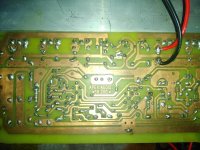
Here is pictures
OK, everything looks good to me.
If I understand correctly, the main concern is lack of bass at the output, right?
Assuming the PSU is powerful enough (some 400VA transformer for both channels or at least 2 x 200VA transformers for dual mono), the only thing that can cut the low frequencies is the DC blocking capacitor at the input.
As I can see, you're using a huge capacitor placed outside the board.
Can you test the amp with just very simple - like a small 10uF electrolytic?
It would be also good to build a Bode plot but you will need an audio analyzer (or a decent sound card with appropriate software like WinAudioMLS, Arta or REW.
APEX SR20 🙂
Hello Mr. Miles and BC109, Please tell what is the right bias for SR20. I am going to make DIY Soundbar with SR20.
Attachments
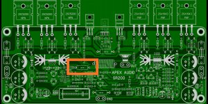
Exactly - this is an indication of high-frequency oscillation. Zobel network resistor burns in this case. This is what I thought was happening in the previous case as well.
How to tame the oscillation - I would talk to Apex, he may have some ideas, statistics, etc. as the designer of this amplifier.
How to tame the oscillation - I would talk to Apex, he may have some ideas, statistics, etc. as the designer of this amplifier.
vzaichenko thanks for helping me sir .plz tell me how to solve this .
Any 1help me about this . because I wasted lots of money and time on this .I made 3 time this amplifier (2 year ) if any 1 can help me then it's good and nice .but If cannot help me to solve this problem (mrs apex ) then it's mean I really wasted time and money .it's my last post on diy audio.
Any 1help me about this . because I wasted lots of money and time on this .I made 3 time this amplifier (2 year ) if any 1 can help me then it's good and nice .but If cannot help me to solve this problem (mrs apex ) then it's mean I really wasted time and money .it's my last post on diy audio.
- Home
- Amplifiers
- Solid State
- Studio Reference Amplifier