
thanks, it looks better on my desk - I made a photo with mobile camera at artificial light. also,when I finish all soldiering I must "wash" copper side with acetone to remove residuals around soldier points. then it will look the best it can 🙂
SR300 has no servo-IC.
congrats...nicely done sir...
please share your experience, i have completed my parts (SR300) but still have no time to work.
if you may what pre-amp are you planning to use with that?
happy new year to one and all!!!
Hello guys today I am very upset.becouse my sr200 is not planning good .I try my best .after reading Dy form. When input is open then burrrrrrrrr sound coming. And feeling less bass.my bais is 26 MV both channel .I give 45 -0-45 ac it's make 63 -0-63 volt dc 8 amp supply.i using good quality capacitor.15000uf 80 volt.i done everything like attached input ground to power ground.but nothing working. Can any I any 1 help me . I spend to much �� on this and time too
Hello guys today I am very upset.becouse my sr200 is not planning good .I try my best .after reading Dy form. When input is open then burrrrrrrrr sound coming. And feeling less bass.my bais is 26 MV both channel .I give 45 -0-45 ac it's make 63 -0-63 volt dc 8 amp supply.i using good quality capacitor.15000uf 80 volt.i done everything like attached input ground to power ground.but nothing working. Can any I any 1 help me . I spend to much money on this and time too
Hi Sunny,post the schematic that is used.Hello guys today I am very upset.becouse my sr200 is not planning good .I try my best .after reading Dy form. When input is open then burrrrrrrrr sound coming. And feeling less bass.my bais is 26 MV both channel .I give 45 -0-45 ac it's make 63 -0-63 volt dc 8 amp supply.i using good quality capacitor.15000uf 80 volt.i done everything like attached input ground to power ground.but nothing working. Can any I any 1 help me . I spend to much money on this and time too
Sunny, also - when you say "nothing works" - what do you mean exactly?
If I understand correctly - you have managed to have zero offsets and 26mV across the outputs' emitter resistors. Is that right?
Is the "brrrrrrrr" sound the only problem?
Schematic (as Thimios already mentioned) and some build photos will help a lot.
Cheers,
Valery
If I understand correctly - you have managed to have zero offsets and 26mV across the outputs' emitter resistors. Is that right?
Is the "brrrrrrrr" sound the only problem?
Schematic (as Thimios already mentioned) and some build photos will help a lot.
Cheers,
Valery

Sunny, also - when you say "nothing works" - what do you mean exactly?
If I understand correctly - you have managed to have zero offsets and 26mV across the outputs' emitter resistors. Is that right?
Is the "brrrrrrrr" sound the only problem?
Schematic (as Thimios already mentioned) and some build photos will help a lot.
Cheers,
Valery
Hello vzaichenko,
1, Yes sunny check the bias across output emitter resistance, but he forget mansion that some time his bias suddenly rise up, and his 10ohm/3watts resistance get too hot or burnt.
2, Without any input signal his speakers produced scary sound like he mansion that.
3, Last time when I listen his sr200 sound quality is so good mid and high sound is very clear I think less bass is 2nd issue for sunny. He use 12"8ohm speakers.
4, how he check the zero offset I think sunny don't know like me.
Sometime some people have so many things in mind but they can't Describe with words.
Sorry for if I wrote something wrong
Regards
Gurpreet
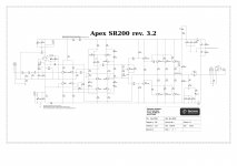
I see the symptoms of oscillation and I probably see the possible reason for it. Attached is the original schematic published by Apex. Note the values of R18 (compensation RC, 1K) and R11 (LTP tail current, 15K) - values on your schematic are different. I've got no sim file to test the parameters, but R11=5K, as stated on your schematic, leads to significantly higher LTP quiescent current, leading to much higher VAS current. Also, R18=2.26 ohm results in different compensation parameters, potentially leading to reduced stability. Is there some good reason for changing the original values?
Attachments
that be my fault I see that he use the simulation file I did a long time ago I did those changes for me to try out but that create a problem to him I apologize for that "this is why I stop coping other people work" a margin of error is higher becuase of that I'm really sorry about that 🙁
Yes vzaichenko, few value are change in schematic and on board,
1. R18 1k same as original schematic
2. R11 8.2 k is lower from original 15k and bigger from jaun schematic 5k.
3.what about R24 10k (on sch. 6.8k) and 18pf capacitor
Now may be sunny can change the with original values.
Regards
Gurpreet
1. R18 1k same as original schematic
2. R11 8.2 k is lower from original 15k and bigger from jaun schematic 5k.
3.what about R24 10k (on sch. 6.8k) and 18pf capacitor
Now may be sunny can change the with original values.
Regards
Gurpreet
Attachments
that be my fault I see that he use the simulation file I did a long time ago I did those changes for me to try out but that create a problem to him I apologize for that "this is why I stop coping other people work" a margin of error is higher becuase of that I'm really sorry about that 🙁
No sir this not your mistake not any other, u are trying something make more batter. You have experience and knowledge therefore u try it. But other side we(sunny,me....) have no big knowledge, we r just copycat 😃😃😌😌
Yes vzaichenko, few value are change in schematic and on board,
1. R18 1k same as original schematic
2. R11 8.2 k is lower from original 15k and bigger from jaun schematic 5k.
3.what about R24 10k (on sch. 6.8k) and 18pf capacitor
Now may be sunny can change the with original values.
Regards
Gurpreet
If you measure at idle, what are the voltage values across the following resistors (referencing your schematic):
V(R25) =
V(R26) =
V(R27) =
V(R28) =
- Home
- Amplifiers
- Solid State
- Studio Reference Amplifier