Hawksford with EF3 ! Join the crowd .... They do sound SO nice. 🙂
OS
Apex PSR150 simulations
This is a sound advice (no pun intended).
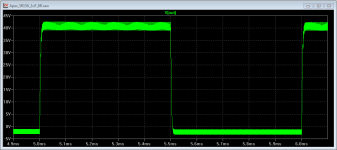
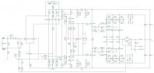
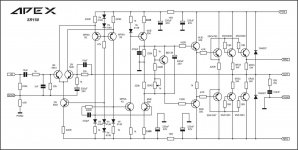
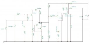
I simulated the SR150 circuit from post #1733 with LTspice IV at a Serbian diyaudio forum (APEX SR150, but I think that the language barrier might be too high for most Members of this forum), and found a tendency towards HF oscillations in the 500-600 kHz range when the model was driving highly capacitive loads, e.g. 2uF//8R (see Att. 1). The input signal was a 2 Vpp square wave at 1 kHz.
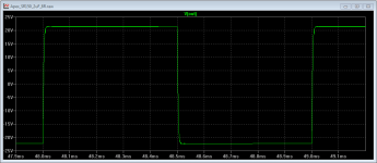
With an LR term of 2uH//4R7 the oscillations are almost eliminated, having an amplitude of about 100mV and a frequency of about 10 MHz (Att. 2, the oscillation is within the line thickness). Note that these are model results; whether the circuit would oscillate at this frequency in a built device can not be answered with certainty at this stage.
These results were confirmed in another simulation performed with the TI Tina software by another forum Member within a joint effort to bring circuit simulation closer to the forum Members, and demonstrate its benefits in the circuit design process.
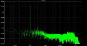
I'm also posting a simulation of the SR150 PSRR. For this one the DC power sources of 50 Volts were both modulated with a 2 Vpp sine component at 100 Hz, whereas the input signal was a 2 Vpp sine at 1 kHz. Apparently, the model has a very good PSRR since the 100 Hz component in the output signal spectrum is situated some 88 dB below the main output signal, being in the case shown lower than 1 mVrms.
If there is interest in the simulation model I would be glad to post it. The transistor models used are freely available in LTwiki.
Regards,
Braca
Does the build already have an Output Zobel?
If so, then you can add a series inductor, but don't go too big.
Try around 1uH and use a resistor to damp it of around 2r2 to 5r6. 9Turns of 1mm to 1.4mm diameter copper wire on a AA battery will be around 1uH.
You can also add another filter to the chassis mounted speaker terminals. 100nF+~4r7 across the terminals should attenuate Radio Frequency (RF) interference coming from the speakers cables sufficiently.
This is a sound advice (no pun intended).
I simulated the SR150 circuit from post #1733 with LTspice IV at a Serbian diyaudio forum (APEX SR150, but I think that the language barrier might be too high for most Members of this forum), and found a tendency towards HF oscillations in the 500-600 kHz range when the model was driving highly capacitive loads, e.g. 2uF//8R (see Att. 1). The input signal was a 2 Vpp square wave at 1 kHz.
With an LR term of 2uH//4R7 the oscillations are almost eliminated, having an amplitude of about 100mV and a frequency of about 10 MHz (Att. 2, the oscillation is within the line thickness). Note that these are model results; whether the circuit would oscillate at this frequency in a built device can not be answered with certainty at this stage.
These results were confirmed in another simulation performed with the TI Tina software by another forum Member within a joint effort to bring circuit simulation closer to the forum Members, and demonstrate its benefits in the circuit design process.
I'm also posting a simulation of the SR150 PSRR. For this one the DC power sources of 50 Volts were both modulated with a 2 Vpp sine component at 100 Hz, whereas the input signal was a 2 Vpp sine at 1 kHz. Apparently, the model has a very good PSRR since the 100 Hz component in the output signal spectrum is situated some 88 dB below the main output signal, being in the case shown lower than 1 mVrms.
If there is interest in the simulation model I would be glad to post it. The transistor models used are freely available in LTwiki.
Regards,
Braca
Attachments
This is a sound advice (no pun intended).
I simulated the SR150 circuit from post #1733 with LTspice IV at a Serbian diyaudio forum (APEX SR150, but I think that the language barrier might be too high for most Members of this forum), and found a tendency towards HF oscillations in the 500-600 kHz range when the model was driving highly capacitive loads, e.g. 2uF//8R (see Att. 1). The input signal was a 2 Vpp square wave at 1 kHz.
With an LR term of 2uH//4R7 the oscillations are almost eliminated, having an amplitude of about 100mV and a frequency of about 10 MHz (Att. 2, the oscillation is within the line thickness). Note that these are model results; whether the circuit would oscillate at this frequency in a built device can not be answered with certainty at this stage.
These results were confirmed in another simulation performed with the TI Tina software by another forum Member within a joint effort to bring circuit simulation closer to the forum Members, and demonstrate its benefits in the circuit design process.
I'm also posting a simulation of the SR150 PSRR. For this one the DC power sources of 50 Volts were both modulated with a 2 Vpp sine component at 100 Hz, whereas the input signal was a 2 Vpp sine at 1 kHz. Apparently, the model has a very good PSRR since the 100 Hz component in the output signal spectrum is situated some 88 dB below the main output signal, being in the case shown lower than 1 mVrms.
If there is interest in the simulation model I would be glad to post it. The transistor models used are freely available in LTwiki.
Regards,
Braca
Nice work,
Regards
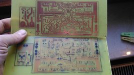
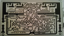

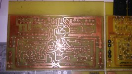
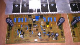
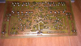
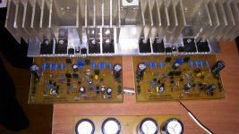
looks much better in my handy,specially a copper side - best toner transfer i ever did!
Nice work,
Regards

SR150ETNA NOVA GODINA!!!
🙂
Happy New Year!!!
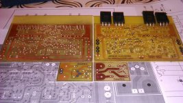
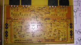
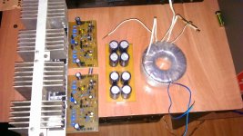
it is not finished yet,but it will be my first project in next year - thanks APEX Audio for all nice projects that made me happy in past years:
NX16 AX12 AX11 F100 HV23 D200 A23 and now SR150
hope to enjoy doing your projects in many years to come!
cheers!
🙂
Happy New Year!!!
it is not finished yet,but it will be my first project in next year - thanks APEX Audio for all nice projects that made me happy in past years:
NX16 AX12 AX11 F100 HV23 D200 A23 and now SR150
hope to enjoy doing your projects in many years to come!
cheers!
Attachments
Last edited:
hi to everyone, i want to make sr 200 amp for my friend and i already make screen for pcb which is made by alex mm but after reading next posts i am confuse which is best pcb for sr 200? one good or may be bad thing in this thread is that there are so many pcb for that amp.i want to make apex pcb but there is no pcb by apex sir for sr 200.i will make apex pcb even it is 20 years old because there is always difference in professional and hobby.need help.
hi respected sir, any pcb layout for this .i didn't make pcb yet for sr 200.what you suggest me for pcb? or i make this sr250.thanks.SR250 with new OS
post1752.
The T1 & T2 drivers are very likely to have different Vgs.
Do the values of R3 & R4 need to be adjusted so that they pass the same current?
Or do we just accept that the 2k2 will pass different currents.
The T1 & T2 drivers are very likely to have different Vgs.
Do the values of R3 & R4 need to be adjusted so that they pass the same current?
Or do we just accept that the 2k2 will pass different currents.
hi respected sir, any pcb layout for this .i didn't make pcb yet for sr 200.what you suggest me for pcb? or i make this sr250.thanks.
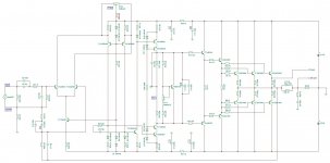
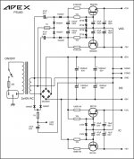
SR200 is a simpler build and does not need the various voltages from supply like is needed from the SR250 circuit.
Regards
GIF , pdf and sprint-file:
Attachments

Last edited:
hi respected sir, any pcb layout for this .i didn't make pcb yet for sr 200.what you suggest me for pcb? or i make this sr250.thanks.
I suggest SR150,
Regards
- Home
- Amplifiers
- Solid State
- Studio Reference Amplifier