oh.. good day My SR200 is working . . . . with four pair output
Congrats... can you post some pictures???
Dear Alex sir, I have gone through the entire project details on SR200. Very Interesting and thank you for you valuable contribution to this DIY Forum. I am ok to built this amp but before starting I need to know on these parameters -
1. RMS watts at 8 Ohms Load - using 4 pair of BJT transistors having DC voltage 66-0-66
2. Slew Rate.
3. Frequency Response.
Or share me a link where I can read more detail on this amp project.
1. RMS watts at 8 Ohms Load - using 4 pair of BJT transistors having DC voltage 66-0-66
2. Slew Rate.
3. Frequency Response.
Or share me a link where I can read more detail on this amp project.
Dear Sir,
Please let me know if any forum member is selling PCBs / spare parts / kits or assemble kits form for SR 200 design. In my place only Bulk PCB production is entertained.
Let me know if a Group buy can be initiated on this forum..
Please let me know if any forum member is selling PCBs / spare parts / kits or assemble kits form for SR 200 design. In my place only Bulk PCB production is entertained.
Let me know if a Group buy can be initiated on this forum..
Actual RMS watts from SR 200
Dear Mr.Alex,
Let me know what RMS watts per channel are expected by using 4 pair of output transistors in SR 200 amp design at 4 and 8 ohms respectively. DC supply would be 66-0-66,15 amp, 1.2 KVA. Total filter caps 40000uF per channel.
..... glad to hear it's working ...... congrats 🙂 Some pictures will be nice.
Regards Alex
Dear Mr.Alex,
Let me know what RMS watts per channel are expected by using 4 pair of output transistors in SR 200 amp design at 4 and 8 ohms respectively. DC supply would be 66-0-66,15 amp, 1.2 KVA. Total filter caps 40000uF per channel.
Power Supply Specs for SR 200 design with 4 pair outputs transistors.
Dear Sir,
I am making SR 200 with 4 output transistors. I need to know the ideal Transformer VAC requirement for best Sonic Quality and Bass response.
My system in process is an active one and will be using separate Amps for High/Mid/Low frequencies - I will be using SR 200 is for Low frequency AMP. For Low frequency module i am using dual 10 inch drivers per channel.
Regards,
Samrat
..... glad to hear it's working ...... congrats 🙂 Some pictures will be nice.
Regards Alex
Dear Sir,
I am making SR 200 with 4 output transistors. I need to know the ideal Transformer VAC requirement for best Sonic Quality and Bass response.
My system in process is an active one and will be using separate Amps for High/Mid/Low frequencies - I will be using SR 200 is for Low frequency AMP. For Low frequency module i am using dual 10 inch drivers per channel.
Regards,
Samrat
...... better ask mr.Mile about this amplifier , I'm one of the PCB designer .I have not built this amp. 😉
Regards Alex.
Regards Alex.
this amp is designed to give 200W at 8R load and about 300W at 4R load. knowing APEX work it can only give you more power than rated.
putting more transistor pairs in output WILL NOT effectly increase output power because more output transistors burdens more the DRIVER transistors and than they become weak link in amplifier.
more transistors at output with the same load as predicted will make driver transistors work as they are designed to,and output transistors will work more relaxed than usual.
for more power you should either increase power supply voltage or put lower resistance load-in both cases there should be more corrections on the driver transistors and the whole amp before them.
put it this way-you can put 500HP engine in toyota yaris,but if you do´t work on chasis,suspension and breaks you will get nothing more than regular one unless you are willing to destroy it.
this amp with two chanels, extra pair of output transistors,transformer with 2x54Vac / +/-75Vdc power supply will need transformer of 800VA for 200W/8R load or 1200VA for 300W/4R load so factor is 2 counting power of both chanel. you can also use a factor of 1,5 but with factor of 2 and extra added pair of output transistors mounted on right heatsink this amp could work just about forever at full rated power (capacitors life would be than "the weakest link in the chain").
Last edited:
Hi,
The SR200 changed with TEF output with multiple pairs of parallel 'powerful' power transistors, can be quiet powerful.
The SR200 is all about great sound quality, The SR200 in my opinion is so nice at high frequencies that maybe its kind of a waste to be only used for Bass, just my opinion.
But I think APEX B500 is a better suite for you.
Regards
Last edited:
that´s right,TEF is the best solution for "torturing" amplifier and using it´s best from basic idea of it´s design.
Dear Sir,
Thank you for your reply. let me know what corrections are required to be incorporated in the Driver stage if I use 2x54Vac / +/-75Vdc, 1.5 KVA power supply with load at 4R.
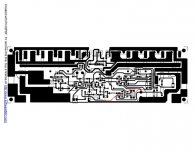
One of the forum member has given me the design of SR 200 and Assembled the PCB for me by using 4 output transistor. Let me know where correction are required. Enclosed below are the PCB with components.
Can you share a link where I can get the the entire project construction pages of SR 200?
Regards,
Samrat


Thank you for your reply. let me know what corrections are required to be incorporated in the Driver stage if I use 2x54Vac / +/-75Vdc, 1.5 KVA power supply with load at 4R.
One of the forum member has given me the design of SR 200 and Assembled the PCB for me by using 4 output transistor. Let me know where correction are required. Enclosed below are the PCB with components.
Can you share a link where I can get the the entire project construction pages of SR 200?
Regards,
Samrat
this amp is designed to give 200W at 8R load and about 300W at 4R load. knowing APEX work it can only give you more power than rated.
putting more transistor pairs in output WILL NOT effectly increase output power because more output transistors burdens more the DRIVER transistors and than they become weak link in amplifier.
more transistors at output with the same load as predicted will make driver transistors work as they are designed to,and output transistors will work more relaxed than usual.
for more power you should either increase power supply voltage or put lower resistance load-in both cases there should be more corrections on the driver transistors and the whole amp before them.
put it this way-you can put 500HP engine in toyota yaris,but if you do´t work on chasis,suspension and breaks you will get nothing more than regular one unless you are willing to destroy it.
this amp with two chanels, extra pair of output transistors,transformer with 2x54Vac / +/-75Vdc power supply will need transformer of 800VA for 200W/8R load or 1200VA for 300W/4R load so factor is 2 counting power of both chanel. you can also use a factor of 1,5 but with factor of 2 and extra added pair of output transistors mounted on right heatsink this amp could work just about forever at full rated power (capacitors life would be than "the weakest link in the chain").
Attachments
PCBs
Dear Sir,
Let me know if PCBs are available for SR 200 with 4 output transistors. If I need to buy the PCB of the Amp, PSU... let me know the source.
Regards,
Samrat
Dear Sir,
Let me know if PCBs are available for SR 200 with 4 output transistors. If I need to buy the PCB of the Amp, PSU... let me know the source.
Regards,
Samrat
APEX SR100 Studio Ref Amp
Hi Alex, If i want to buy some pcbs like SR-200, PSU etc... let me know the source for buying these products.
...... better ask mr.Mile about this amplifier , I'm one of the PCB designer .I have not built this amp. 😉
Regards Alex.
PCB's?
..... sorry but I have no PCB's to sel , or a source ...... It's Diy not commercial project , so try to make yourself .....🙂 I wish you success 😉
Regards ,Alex
..... sorry but I have no PCB's to sel , or a source ...... It's Diy not commercial project , so try to make yourself .....🙂 I wish you success 😉
Regards ,Alex
SR800
Mr. Mile,
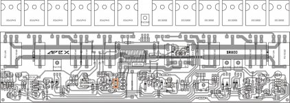
Is the SR800 been tested? please advise the value of this part marked in orange.
Thanks...
Regards,
Mr. Mile,
Is the SR800 been tested? please advise the value of this part marked in orange.
Thanks...
Regards,
Attachments
Last edited:
DB3 Diac SeriesBreakover voltage
3: V typ = 32V
http://www.electronicecircuits.com/wp-content/uploads/2010/04/DB3-Diac-trigger-diode.jpg
3: V typ = 32V
http://www.electronicecircuits.com/wp-content/uploads/2010/04/DB3-Diac-trigger-diode.jpg
- Home
- Amplifiers
- Solid State
- Studio Reference Amplifier