Did you mean you checked the filaments.....not the cathodes....you shouldent have something to measure in the order of Amps on the cathodes....filaments yesJeff,
I checked the cathodes, and they drain 1.66 A with only the KT88 and 2.24 A with KT88 + 6N1P. What is a bit high is the voltage, as I read 6.8 V without load and it drops only to 6.7 with the load.
[/QUOTE]I saw that when everything is connected the AC of the heater of the rectifier is only 2 V.[/QUOTE]
This is low....
[/QUOTE]What about the resistance of the HT secondary ? I measure only 37 ohm between 0 and 360 V.
[/QUOTE] Not to sure this is that critical...
You didn't possobly hook the B1+ to the driver and the B2+ to the power tube did you?
Glad you figured out the choke, you hum should dissappear now....
You have a weird problem going on indeed, I need to think more on it. Best way to apprach this is to try to figure out how to acheive what you are measuring if that was what you were trying to do, kinda reverse engineering it.
The problem with the driver dropping to 130V while the power tube staying at 460V should only hold true if the current through the KT88 was higher than normal, not lower than normal like you have.
How did you measure the current going through the KT88? Or have you done this yet. A good stock of precision 1R 5-10 watt resistors is good for this sort of thing, just place one in series with what you are trying to measure and do as I mentioned earlier in the thread.
I could definitely see the driver B+ dropping a few tens of volts if the current through the KT88 was extrodinarily high....but again, not if it were low.
We will figure this out......
Jeff
CCS on driver tube
I recently found there very economical CCS kits at K & K, here:
K & K Audio - Lundahl Transformers, audio DIY kits and more
I went ahead and bought 4 of them, 2 for the KT88SE I just finished, and the other 2 for a 2A3 SET I am starting to build.
I was wondering what one would recommend setting the current at for both the 6N1P and/or the 6922/6DJ8 ?
Also, once I get this installed it should be fairly easy to tube roll between types. Are there any other driver tubes with the same pinout that might work well in this KT88SE?
I also recently bought several red LEDs. I was wondering exactly how one hooks these up on the driver tube? Do you keep the bypass cap in place with the LEDs. Also, there is no sense in keeping the bypass cap in place with the CCS is there (shouldn't be), but is it okay to leave it there if I don't want to unsloder it?
The KT88SE is still running perfectly. I have about 80 or so hours on it now. It does seem to sound better as it burns in. I noticed less distortion and the ability to turn the volume higher without distortion on some of the same songs I listened to at first and then now.
Although I have an additional 1K resistor floating in parallel an not connected to the 1K on the driver (to bring it to 500 when connected) I have yet to connect it to try the 6922. I think I will do this tonight. The CCS won't be here for a few days.
As far as setting the current on these CCS, I was planning on placing a 1R resistor in series and measuring the mV, as I have mentioned earlier. Does anybody know of a simpler method in doing this?
Thanks again,
Jeff
Jeff, yes I mean I have 1.6 A current in the heaters.
I could measure the current drained by the kt88, as I have the RC filter in the output stage of the power supply. with only one channel attached the drop on this resistor tells me the total current drained. but I will go to buy some 1 ohm resistor today.
I also have around 10 V drop on the opt.
The B1+ and B2+ are hooked correctly.
So when the rectifier is not installed I have 5.7 V on the heater, when I put it in I measure 2V (AC). I did not try to change the 5V source yet, but I am not sure that this measurement is very reliable, as when the rectifier is connected I have HT there. I can try to see with the scope what happen. I tried the kt88 on the elekit, and they work fine (but I did not do any measurement) the only think I did not test is the rectifier.
If I put my numbers in the weber calculator, I get exactly the value of the current I see it is drained. Now following the reverse engineer approach, that makes a lot of sense, you do I change the the working point of the tube ?
From what I understand the coupling capacitance should make the driver and the kt88 independent from what concern the DC, so I have only three things: the value of the HT, the cathode resistor and the grid resistor. Is it right ?
I have also a pair of 6l6g that I can try.
Thanks,
Davide
Se kt88
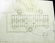
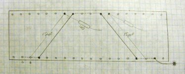
I've included my schematic and tag board layout. The schematic is a hybrid from porkchop, kegger (AK), and AlexG. Thanks a million guys, and thank you jmillerdoc too for the generous advice!
Here is my PSUD2 scenarios: (398V estimate open voltage of Hammond 375-0-375V PTX, all PSU caps ASC)
1. 375VPTX - 5U4G - 10uF - 10H - 100uF. B+ = 414V, Ripple = 0.14V
2. 375VPTX - 5U4G - 20uF - 10H - 100uF. B+ = 419V, Ripple = 0.07V
3. 375VPTX - 5U4G - 40uF - 10H - 100uF. B+ = 420V, Ripple = 0.033V
4. 375VPTX - 5U4G - 40uF - 10H - 50uF - 100R - 50uF. B+ = 402V, Ripple = 0.014V
Just a few questions:
1. How are the tag board layouts for lowest hum potential?
2. Before the 6NP1, which RC filter is better: 250R + 10uF, 100R + 15uF, or 100R + 47uF?
3. Should I use 1kR before the input grid of the KT88? If so, does the 1.2kR before OPT tap or 220k grid leak resistor change?
4. Would adding a 150-250uF cap on B+ before OPT help with dynamics and transients?
5. Is it OK to use 2 separate twisted pair of heater wires going to 6N1P and KT88 pair?
6. For the T, UL, P mode switch, would a 3A 250V minature SP3T toggle switch be OK? (BTW, the pin diagram for the switch on layout is arbitrary)
7. Whats the best value coupling cap: 0.22uF or 0.33uF?
8. Has anyone tried a 6BQ7 tube in place of the 6N1P?
9. At what clock position of the tubes guide pin do you get the most glow?... I have the tubes oriented as shown on my tag board layout. This is my first build and first tube experience so I have no idea! I am a 4 month newbie to tube circuits.
Thanks!
Attachments

Last edited:
Mine's different but......
I built mine a little different. You have a few things on yours I omitted, I basically used the schematic at the beginning of the thread. I will try to answer the questions I think I have a grip on though...
1) I think you did the tagboard great. The driver stage, pot, and RCA inputs are all nicely seperated from your filament supply, etc...I was much more careless about this but I put DC to my filaments that was rectified and smoothed with over 9KuF. I also ran my inout wires from the back of the amp, right under the power trafo all the way to the front where the pot is and then to the driver tubes (I used 2, 1/2 of 1 for each side) on either front corner of my amp. All inout wires are silver wire and double shielded with all shielding starred at the main earth gnd. I have not noise or hum, period. Not sure if it is b/c of the DC or the shielding but I was much more careless about layout for the sake of aesthetics and it sounds perfect. I would re-consider the placing of a power resistor on either side of your 220uF....electrolytics are very sensitive to heat. I would put the cap all the way out to the edge, closest to the 3K.
2) I guess that depends on what you are after...I presume the least amount of ripple. If that is the case I would go with the 100R+47uF. I used a 30H 595 DCR choke and a 15uF cap, again...worked perfect, no motorboating.
3) I used the 1K grid series resistor, no change to the 220K leak resistor. I did not use the 1.2K you mention....works fine and is one less noisey resistor.
4) Again, mine is different but I went with this theory and put 162uF. I didn't compare it to a circuit without it so I can't be for certain it helped for dynamics (definitely helps decrease ripple). I am afraid if you add the whole 150 or 250 (mine was a total of 162 where 100 was intended) you will start having problems with exceeding the rectifiers forward current, check it in PSUD2 first.
5) why not? I did.
6) Should be fine. The voltage might be higher but the current rating of 3A should keep that in check. I used a similar rated rotary.
7) Again, best is in what your are measuring. You will pass lower frquencies with a bigger cap. 0.33uF would be "best" although 0.22 should work ok if that is what you have on hand.
8) no, not a 6BQ7. I did try the 6DJ8 with the cathode resistor set at 1K. It sounded off and I have intentions to place a switch similar to the one at the cathode of the KT88 to drop it to 500R.
9) Wife is asleep in the bedroom where the amp is, that one will have to wait till the morrow 🙂
Hope that was helpful.
Jeff
1. How are the tag board layouts for lowest hum potential?
2. Before the 6NP1, which RC filter is better: 250R + 10uF, 100R + 15uF, or 100R + 47uF?
3. Should I use 1kR before the input grid of the KT88? If so, does the 1.2kR before OPT tap or 220k grid leak resistor change?
4. Would adding a 150-250uF cap on B+ before OPT help with dynamics and transients?
5. Is it OK to use 2 separate twisted pair of heater wires going to 6N1P and KT88 pair?
6. For the T, UL, P mode switch, would a 3A 250V minature SP3T toggle switch be OK? (BTW, the pin diagram for the switch on layout is arbitrary)
7. Whats the best value coupling cap: 0.22uF or 0.33uF?
8. Has anyone tried a 6BQ7 tube in place of the 6N1P?
9. At what clock position of the tubes guide pin do you get the most glow?... I have the tubes oriented as shown on my tag board layout. This is my first build and first tube experience so I have no idea! I am a 4 month newbie to tube circuits.
I built mine a little different. You have a few things on yours I omitted, I basically used the schematic at the beginning of the thread. I will try to answer the questions I think I have a grip on though...
1) I think you did the tagboard great. The driver stage, pot, and RCA inputs are all nicely seperated from your filament supply, etc...I was much more careless about this but I put DC to my filaments that was rectified and smoothed with over 9KuF. I also ran my inout wires from the back of the amp, right under the power trafo all the way to the front where the pot is and then to the driver tubes (I used 2, 1/2 of 1 for each side) on either front corner of my amp. All inout wires are silver wire and double shielded with all shielding starred at the main earth gnd. I have not noise or hum, period. Not sure if it is b/c of the DC or the shielding but I was much more careless about layout for the sake of aesthetics and it sounds perfect. I would re-consider the placing of a power resistor on either side of your 220uF....electrolytics are very sensitive to heat. I would put the cap all the way out to the edge, closest to the 3K.
2) I guess that depends on what you are after...I presume the least amount of ripple. If that is the case I would go with the 100R+47uF. I used a 30H 595 DCR choke and a 15uF cap, again...worked perfect, no motorboating.
3) I used the 1K grid series resistor, no change to the 220K leak resistor. I did not use the 1.2K you mention....works fine and is one less noisey resistor.
4) Again, mine is different but I went with this theory and put 162uF. I didn't compare it to a circuit without it so I can't be for certain it helped for dynamics (definitely helps decrease ripple). I am afraid if you add the whole 150 or 250 (mine was a total of 162 where 100 was intended) you will start having problems with exceeding the rectifiers forward current, check it in PSUD2 first.
5) why not? I did.
6) Should be fine. The voltage might be higher but the current rating of 3A should keep that in check. I used a similar rated rotary.
7) Again, best is in what your are measuring. You will pass lower frquencies with a bigger cap. 0.33uF would be "best" although 0.22 should work ok if that is what you have on hand.
8) no, not a 6BQ7. I did try the 6DJ8 with the cathode resistor set at 1K. It sounded off and I have intentions to place a switch similar to the one at the cathode of the KT88 to drop it to 500R.
9) Wife is asleep in the bedroom where the amp is, that one will have to wait till the morrow 🙂
Hope that was helpful.
Jeff
Jeff, thank you very much for such an in depth response! I will make those changes. Alexg thought the same, however, if I use the 100R + 47uF RC, can I use just one RC circuit for both channels since the 47uF 630V Solen is large?... Even though I don't know how much ripple is acceptable for classical music, I'll use this PSU:
375VPTX - 5U4G - 40uF - 10H - 50uF - 100R - 50uF. B+ = 402V, Ripple = 0.014V
I am still eager on your thoughts with the proper 6DJ8 substitution. If it's worth while, I may incorporate a switch too. I heard that the 6BK7, 6BQ7, and 6BZ7 are drop in equivalents for the 6N1P, that's why I was asking if they might work in the circuit. It seems so tempting since NOS for these tubes are so cheap @ $5 (including shipping).
I must credit Glenn for the inspiration on the tag board overall layout.
Thanks again!
Your tagboard looks great!
I only use this type of construction because I started this hobby building guitar amps. Strange how these hi-fi amps are a lot more tricky to build 🙂
Please post some pictures when you have your build complete.
I haven't tried a 6DJ8 yet, but hope to get to that over the holidays. Work keeps getting in the way of my hobbies 😀
I think that the big ASC motor run caps play a big part in keeping noise down in the power supply. I've heard other people try this amp using electrolytics and the noise is much worse. I can't hear any sign of noise with my ear right up to both the woofer and horn in my A7's.
Good luck.
Glenn
The chicken and the egg
I am still puzzeled with my problem of the KT 88 not draining enough current.
I completly rebuild the power supply stage, now I can have CLC or CLCRC, just replacing the R with a wire. I have the following values
C 10uF(Polypropilene) - L 10H/dcr81ohm - C 47uF(Film) - R (testing) - C 47uF(Film)
When R=0 the two capacitors are in parallel and basically I have the power supply as was in the original project by Alex.
I am using a 5U4GB (planning to try one with a higher drop) .
The transformer is 360 0 360 rated for 0.260 A. I measure 389 V without load . PSU calculates an impedence around 70 ohm. I added two 50 ohm 10W resistors before the plates of the rectifier to increase it a bit.
Now when I switch on the amlifier, the voltage goes up to 550 V, and after few second starts to go down. After around 10 seconds I arrive to an equilibrium of 465 V I tried to put a 500 ohm resistor and it goes down to 445.
Now 20 V drop on 500 ohm resistor...Mr. Ohm told me that around 40 mA are passing.
If I see the chart of the KT88 this is kind of normal. The higher the voltage, the lower the current. But I was relying on the current drained by the KT88 to bring the voltage down. How to do ? Does it mean maybe that the HT goes up too fast comparing to the filaments ?
I am planning to attach a lab power supply to the filaments, let them run for a while and then switch on the HT. Let's see what will happen.
Next thing I will try is to increase the resistors before the plates. and or reduce the first capacitor to 4.7 uF
After this I will just look at it and scratch my head. :-(
Davide
More test
Yesterday I tried to power the filaments with an external power supply, the display was showing 6.4 V 2.4 A. Then I powered the HT, but the behaviur of my amplifier did not change.
Do you think it is possible that during all these tests I just damaged the tubes ? Any low tech way to test it ?
Thanks,
D.
I put a new rectifier, with higher voltage drop. got only 5 volts less.
I think I am going to redo one channel from scratch.
D.
I think I am going to redo one channel from scratch.
D.
PROBLEM SOLVED !!!
My mistake, like an idiot I had a resistor of 1 Mohm instead of 100 ohm connected for the ultra linear. I don't even know how I got these resistor, as I did not buy them (or at least I did not ask for them). Unfortunately they were the only components a bit difficult to measure in my layout.
I still have a bit of hum that I have to figure out, but at least not the voltages are correct.
Good night and thanks to everybody for help.
Davide
Let me be the first to say: See how easy that was? 😎
Congratulations on your success. So how does it sound?
Congratulations on your success. So how does it sound?
PROBLEM SOLVED !!!
My mistake, like an idiot I had a resistor of 1 Mohm instead of 100 ohm connected for the ultra linear. I don't even know how I got these resistor, as I did not buy them (or at least I did not ask for them). Unfortunately they were the only components a bit difficult to measure in my layout.
I still have a bit of hum that I have to figure out, but at least not the voltages are correct.
Good night and thanks to everybody for help.
Davide
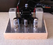
So let's show some pictures !
The sound is good !! Although I am just letting it play for a while before listening with real attention.
Some notes on my experience with this first project. The part of understanding the schematic has been the easiest and quickest. What really took me a lot of time was figure out how to put things together.
First of all I had to choose the components, and this changes things, as the size of a capacitor changes dramatically if you replace film with polypropilene and electrolitic.
I was also very much concerned about safety. I had no idea how close to a plate a contact with 400 V could be. This is why at the end I decided to have the upper metal plate machined and prepared, but on the other side I mounted everything on some smallest plastic plates. It also allows me to remove independently ch L, ch R and PSU. I will make it even better next time, as this came in progress. Like this I can also have very few holes in the upper plate, for esthetic reason.
I will now rest a bit and listen, then I plan to test the following:
1) DC for filament. I have two regulators ready, but I want to test them a bit before putting them in.
2) Snubber capacitors on the PSU capacitors. Question: should I go for 1/100 1/100
3) Leds on the cathodes of the drivers. Although I like the LM317 approach more, as with a potenziometer it gives much more possibility to play around.
Question: How do you match the led ? Just with the tester in diode mode or you put a current through them and measure the voltage ? It should be the same, but numbers come different.
4) I have to find a decent 560 ohm resistor. As in reality they are around 570 ohm and are quite different between each other. I have two 500 ohm 1%, but maybe it's not enough. I have the 3K in parallel.
Question: where is better to put the 1M ohm resistor for the input, close to the connector or close to the tube ? I don't really have a ground close to the tube.
Another question: how did you do the grounding? To have flexibility I have one cable for each component (connector, driver cathode, kt88grid, kt88 cathode) plus power supply, socket earth and transformer earth.
Yesterday they were just all tied together with a screw and I could measure 6 V AC on the plate (No good)
Now I have the following configuration:
a) Socket earth and transformer earth connected together in point 1 to the plate.
b) Power supply connect to point 2 to the plate
c) All the other connected to point 3A and 3B, one for each channel.
The secondary of the OPT is not connected to anything and is isolated from the plate.
Does it make sense ?
The only strange thing is that my oscilloscope picks a lot of high frequency (in the MHz range) when connected to the secondary.
Next project I would like to make a monoblock with the Jean Hiraga design posted on diyaudioprojects. I am not 100 % sure that project is correct, mostly the PSU stage. Anyone joining me ?
Finally, I wanted to dedicate all this work to my son Daniel, that was born on 7 of December. I wanted to played it for him when he arrived home, but he had to wait some more days. I will write his name in Japanese on the front of the ampli. 🙂
Have a great WE,
Davide
Attachments
Jeff, by the way, when your switch is in one of the null positions, you should have very similar reading like I had with the 1 M ohm resistor. That;s why it sounds horrible 🙂
D.
D.
First off, congratulations on the birth of your son!
The amplifier construction looks very nice, well though out.
I can't comment on many of your questions as I am also new to this construction. I am still waiting on OPTs to be able to finish.
I am using a Caddock (Resistors - Caddock High Performance Film Resistors) 560 ohm, 15 watt power film resistor with the chassis being the heat sink.
I have a single point ground. All ground connections will go directly to this point, including the AC mains ground.
I do know that any loose ground connection can potentially cause varying degrees of interference problems.
I am not using an input attenuator so I have 100K to ground on the signal input connectors.
So let's show some pictures !
The sound is good !! Although I am just letting it play for a while before listening with real attention.
Davide
Last edited:
I am thinking of getting rid of some of the ground wires. I tried to shorten the ground at the components location and did not hear any difference, but I will check with the oscilloscope before cutting.
The ampli is playing now, I still have to finish some details inside, but now that it works, I feel kind of lazy.
D.
The ampli is playing now, I still have to finish some details inside, but now that it works, I feel kind of lazy.
D.
Star ground works best for me and the simplest.
The amp turn out NICE!
Can we take a peak of the underneath?
The amp turn out NICE!
Can we take a peak of the underneath?
- Status
- Not open for further replies.
- Home
- Amplifiers
- Tubes / Valves
- stereo SE kt88 build ... abdellah diyaudioprojects design