Just curious, any harm in leaving pins 1 and 8 tied together when not using the EL34 tube. OK to leave them tied together with the KT88 or 6L6 tube on the amp?
hello alexI have tried KT88, 6550, EL34 and 6L6. The 6L6 did not cut it on my personal sound preference, but the rest is gorgeous. I used a pair of Siemens El34, Tungsol 6550 (reissue) and NOS GE 6550, as well as EH KT88, NOS GEC KT88 and reissue GEC KT88.
My favorite for vocals is the Siemens EL34 and the KT88's and the 6550's for the rest of my music.
i resently used your schematics in a fairly simalar disign [transedar ugt,s and a amroh power trafo]
i use a 5u4gb as rectifier and a 6n23p[1971 voskhod] as driver,old tesla el 34 in triode ,what is the advantange of using a 560 r cathode resistor for the el34 ?
if i go to the datta in the psu from duncan ,i find a 370 ohm for el34 se triode mode ,if i use 2 1,7 volt leds as a kathode resistor for the 6n1p ,do i use then also the elco wich is over the risistor of 1 k in the schematics ,can you draw a small schematics with the leds ,when i see it ,i can better understand it ? i am a bit of a newbie ,and don,t have so much tube knowledge
greetings ko [seel34]
Pin 1 on the 6L6 and KT88 is unused, so yes, you can leave them tied together.
Just curious, any harm in leaving pins 1 and 8 tied together when not using the EL34 tube. OK to leave them tied together with the KT88 or 6L6 tube on the amp?
hazen grid modification
i used a hazen grid modification on my amp wich gave good sonic improvements ,for the ones who use el34 in triode ,i would recommend trying it
here are the 2 articles from steve deckert ,on the hows and working
DECWARE - The Hazen Mod
DECWARE - The Hazen Mod
here is the discusion about it
Forums - The Christmas comes early mod!
by putting a condensator 0,1 uf between 600 volt between pin 1 and 8 of the el34 grtz ko
Seel34-
I also used a 560R resistor for use with a KT88 tube as this amp was originally designed. I did this because the bias was a little to hot for my amp, of course this depends on your B+ voltage.
I actually parallel a 3k resistor in (470R total) for use with EL34's as it gives me a slightly lower plate dissipation, 19W vs. 24W. I just felt more comfortable using a slightly lower bias to make the EL34, KT66, 6L6 power tubes last a little longer.
Glenn
EDIT:
The link for LED biasing I did on my amp is located here:
http://www.audiokarma.org/forums/showthread.php?t=262279
Post #5
Last edited:
Scheme and rectifier
I think that I was not clear on my porpouse in posting my scheme, and I created some confusion.
Actually I am going to implement the amplifier following the electrical scheme of the first post. The only modifications that I would like to try are:
1) diodes on the catode of the driver
2) I catode resistor of the KT88 to 500 ohm, just because I could not find a 560 ohm 10 W one. I will try like this, if I get in trouble I will add a resistor in series.
3) I added polypropylene capacitors in parallel with the catode capacitor.
The initial reason why I send my scheme, is that I realized that was not really trivial to find a layout for the components in the cabint in order to have a bit of order inside the chassis and reduce the interferences, so I wanted some comment on the distribution of the components I drew.
How big are your chassis ? I want to mount everything on a single plate and I get fomething like 40 X 35 cm.
Also I was wondering how you do with the grounding, I am planning to have an indipendent wire for ground for each part of the circuit(driver catode, kt88 catode, k88 grid and driver plate filter) and to connect them all in a single point. This to avoid ground loops, and to have the possibility to make current measurements in an easy way.
Last thing, I found the following browsing about the rectifier:
3) If Capacitor loaded, you must have a minimum required copper resistance of the transformer winding.
"
This is an old design rule, obligatory for any 5U4G, EML or other brand. If capacitor loaded, the first capacitor must be chosen at or below the maximum value in this data sheet. At EML we adapted to the same values from old data sheets. So there will be no doubt about those values. The minimum resistance is specified for the complete winding. (So not measured from the center tap). In case you use a transformer with too low copper resistance, you need to add one series resistors in each HV winding connection of the transformer. Then, with those two resistors in series, you re-measure the transformer winding, and the result must be as follows:
Raa, value, for Curves 1...6: minimum 170 Ohms
Raa, value, for Curves 1...8: minimum 230 Ohms
"
Now I could find in the datasheets the story of the max capacitance, but not the story of the max resistance. I am using a 5U4GB, and I have 40 ohm of DCR. far below what is requested. Any additional information?
Best Regards,
Davide
thankyou for the infoSeel34-
I also used a 560R resistor for use with a KT88 tube as this amp was originally designed. I did this because the bias was a little to hot for my amp, of course this depends on your B+ voltage.
I actually parallel a 3k resistor in (470R total) for use with EL34's as it gives me a slightly lower plate dissipation, 19W vs. 24W. I just felt more comfortable using a slightly lower bias to make the EL34, KT66, 6L6 power tubes last a little longer.
Glenn
EDIT:
The link for LED biasing I did on my amp is located here:
KT88 SE Abdellah (modified by Alex Gendrano) - AudioKarma.org Home Audio Stereo Discussion Forums
Post #5
looks very intresting this led biasing , what would be the correct leds for ecc88,e88cc /6n23p,is there a general value [2volts????]i am still tunning my amp and trying by tube rolling to get the right sonic configuration at this momemt its tesla e88cc tesla [the real old ones not jj wichts is not tesla]tesla el34 brown based ,5u4 svetlana [sint petersburg produced 11/1960 black plate] the factory nowadays is called winged c ,what nowadays is markt as svetlana is made in the reflector factory wich is a total diferent quaility of tubes ,
i used to use 680ohm resitors for the 6n1p and 370 ohm for the el34 in triode
only in this configuration , my preamp part gave to less amplification ,tryed a srrp with 6n1p but that was to much ,and gave easely defrormation of the sound ,with the alex configuration the amplification is good although i think
when i open de amp to put the leds in i will put in a a switch , so i can change from 560 ohm to 370 ohm ,for the el34 in triode
i find this a very intresting forrum , thanks to everybody for there input
to created this amp kind regards se el 34
greeting ko
helloSeel34-
I also used a 560R resistor for use with a KT88 tube as this amp was originally designed. I did this because the bias was a little to hot for my amp, of course this depends on your B+ voltage.
I actually parallel a 3k resistor in (470R total) for use with EL34's as it gives me a slightly lower plate dissipation, 19W vs. 24W. I just felt more comfortable using a slightly lower bias to make the EL34, KT66, 6L6 power tubes last a little longer.
Glenn
EDIT:
The link for LED biasing I did on my amp is located here:
KT88 SE Abdellah (modified by Alex Gendrano) - AudioKarma.org Home Audio Stereo Discussion Forums
Post #5
my b+ is 350 volt , i measure with the 560 ohm with cap minus 25 volts on the kathode of the el 34 , do you still think it is advicable to put a 3k paralel
thnx and kind regards
ko
thnx glen
great program , if i did it right ,i am in 43 ma ,in the green ,560 is the right resistor by b+ 350volts [ 338 on the tube ] and 25neg by the cathode
thnx again greetings ko
great program , if i did it right ,i am in 43 ma ,in the green ,560 is the right resistor by b+ 350volts [ 338 on the tube ] and 25neg by the cathode
thnx again greetings ko
Yes, that calculator is very handy. You can play around with different voltages/resistor values to see how it affects the current through the tube.
Good luck!
Glenn
Good luck!
Glenn
Quick questions: I have two 6.3 secondaries in my power transformer.
How would you connect them ? Left and right or preamp and amp ?
Additionally, I understand that if I want to put a switch to change between triode and ultralinear, it has to be rated for 400 V. Am I right ? Do you operate it while the system is on ?
Sorry for all this questions, but I am really getting close to the end of the assembly, and details are killing me !! I'll share results soon.
Best Regards,
Davide
Thanks,
Davide
Questions are great!
Your questions are great ones......
I hooked mine up Left/Right and I used self-made DC Filament modules, I don't really think the former matters (L/R) so much though. I did it this way for the sake of balance for the modules. If I had done it Pre-amp/Power tube one module woulde have been different from the other in terms of calculating voltage dropping resistors and such. Depending on the current rating of the 6.3v secondaries, it should not make too much difference.
The switch carries very little current on the mode selector. I just used a non-shorting, break before make, standard 2 pole 6 position selector from AES (3 of the positions are null setting without any connetion to the g2, I just don't turn it that far). It works fine and I have swithched it while in operation without incident (no load pops or noises, very quiet while switching).
I also used a SPDP toggle for the cathode parallel resistor (one pole for each side).
This is how I did it, whether or not it is "right", some may have issues with it. It seems to work just fine though for me.
I have plans to place some sort of "block" on my rotary selector for the 3 modes (I did all 3, UL-pentode-triode) so you can't turn the knob to the null positions. I tried listening to it with the g2 at the nulll position (no connection on g2) and it sounds terrible....go figure.
Jeff
Quick questions: I have two 6.3 secondaries in my power transformer.
How would you connect them ? Left and right or preamp and amp ?
Additionally, I understand that if I want to put a switch to change between triode and ultralinear, it has to be rated for 400 V. Am I right ? Do you operate it while the system is on ?
Sorry for all this questions.......
Your questions are great ones......
I hooked mine up Left/Right and I used self-made DC Filament modules, I don't really think the former matters (L/R) so much though. I did it this way for the sake of balance for the modules. If I had done it Pre-amp/Power tube one module woulde have been different from the other in terms of calculating voltage dropping resistors and such. Depending on the current rating of the 6.3v secondaries, it should not make too much difference.
The switch carries very little current on the mode selector. I just used a non-shorting, break before make, standard 2 pole 6 position selector from AES (3 of the positions are null setting without any connetion to the g2, I just don't turn it that far). It works fine and I have swithched it while in operation without incident (no load pops or noises, very quiet while switching).
I also used a SPDP toggle for the cathode parallel resistor (one pole for each side).
This is how I did it, whether or not it is "right", some may have issues with it. It seems to work just fine though for me.
I have plans to place some sort of "block" on my rotary selector for the 3 modes (I did all 3, UL-pentode-triode) so you can't turn the knob to the null positions. I tried listening to it with the g2 at the nulll position (no connection on g2) and it sounds terrible....go figure.
Jeff
BTW, if anybody has a good source for a 2 pole 3 position rotary selcetor, please do tell. I searched all of the major outlets I am aware of and couldn't find one. There is one at VT4C.com but they want about $35 for it. It is some fancy German made, silver contact job....thought a bit of overkill here....
Jeff
Jeff
This is what I used for a source selector when I built my preamp. You adjust the # of positions available, 2 to 6, by use of a keyway. Contacts are non-shorting, silver plated brass.
C4D0406N-A Electroswitch Rotary Switches
C4D0406N-A Electroswitch Rotary Switches
BTW, if anybody has a good source for a 2 pole 3 position rotary selcetor, please do tell. I searched all of the major outlets I am aware of and couldn't find one. There is one at VT4C.com but they want about $35 for it. It is some fancy German made, silver contact job....thought a bit of overkill here....
Jeff
Thanks, I'll take it easy on the switches. Here in Tokyo I found 3 positions 2 ways, but they are rated for 30 V.
Another issue that I have open is the resistance of my secondary. I measure 39 ohm between center and 400V. The rectifier would like to have 21ohm at 350 V and 67ohm at 450. Do you think I should just leave it like this or add a series resistor. In case how do I connect them? I would put two 20 ohm 25 W resistors per phase.
Thanks,
Davide
BTW, if anybody has a good source for a 2 pole 3 position rotary selcetor, please do tell. I searched all of the major outlets I am aware of and couldn't find one. There is one at VT4C.com but they want about $35 for it. It is some fancy German made, silver contact job....thought a bit of overkill here....
Jeff
i do not know what the sending cost are to amerika ,but the switches are really cheap [its a electonic army surplus store in ymuiden the netherlands
and the do ship ]
Baco Army Goods - Productgroep: Schakelaars
grtz taz

just finished the amp. sounds very nice with el34 [old production tesla,s]in triode with the hazen grind modification ]
driver 6n1p voskhod 6n1p ev and a 5u4 1960,s svetlana sint peterburg produced black plate rectifyer] the 6n1p is led biased
grtz ko
driver 6n1p voskhod 6n1p ev and a 5u4 1960,s svetlana sint peterburg produced black plate rectifyer] the 6n1p is led biased
An externally hosted image should be here but it was not working when we last tested it.
grtz ko
Last edited:
So, the good news is that I just finished my first tube amplifier (I had done the Elekit TU 879, but it's a kit, does not really count). I did not blow up anything, including myself. I just had a kindly reminder by one capacitor, about how unpleasant electricity can be...bleeder resistor for ever.
Here is how it looks like (without underwear) [IMG_1219.jpg]
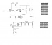
Anyway there is something that is not right, and I don't manage to figure how what. On the graph you can see the voltage reading that I have (referred to ground).
I have a B+ that is higher than expected, as it looks like the tube drain less current than they should be. I have very similar readings for channel L and R. Switching between UL, triode and pentode does not change anything.
Each ground has its own wire, and now are all tied together in a single point.
I can tweak the B+ to get to 400 V, I am not sure this is the way to go. I would really appreciate some advice.
Best Regards,
Davide
Here is how it looks like (without underwear) [IMG_1219.jpg]
Anyway there is something that is not right, and I don't manage to figure how what. On the graph you can see the voltage reading that I have (referred to ground).
I have a B+ that is higher than expected, as it looks like the tube drain less current than they should be. I have very similar readings for channel L and R. Switching between UL, triode and pentode does not change anything.
Each ground has its own wire, and now are all tied together in a single point.
I can tweak the B+ to get to 400 V, I am not sure this is the way to go. I would really appreciate some advice.
Best Regards,
Davide
Attachments

- Status
- Not open for further replies.
- Home
- Amplifiers
- Tubes / Valves
- stereo SE kt88 build ... abdellah diyaudioprojects design