Yes, Jeff, I realize the 6N1P tube is too far back in pix. I am planning on placing the RCA jacks on the left side for a short signal path. I figured that having the rectifier closer to the caps might be better than having them closer to the PTX. I am not worried about heat as much as I am hum and noise.
You're right, I may have to submerge C1, since it's going to be determined experimentally, as I am planning trying out values from 10uF to 40uF to get a desired output of 400-420 B+. I need to get wider 2.6in x 0.75in red oak veneered wood.
Those copper ventilated socket plates look awesome! But, truthfully, I am going see how this first build turns out. I don't want to put the cart before the horse. If it sounds good, then I'll build a fancier looking build with more aesthetic chassis components - like the Derek Walton 300B SET amp.
Well, I got it all together last night. Haven't hooked it to a source yet. I found my B+ was for by a margin of about 35V (435V) from the PSUD2 simulation. I went ahead and changed the resistor before the driver stage on the power supply to a 30H 595DCR choke. This gets my B+ at the driver stage down to about 410V. I am going to add a resistor between the10H choke and the 80+82uf caps, gonna try about 20R to begin with and go from there to get the B+ down to about 400-410. I could have hooked it up tonight but I want to wait until I get the voltages right. Other than that all of the connections and switches work fine on the power tube cathode resistors (560+3K) and the selector for UL, triode, and pentode modes. I also had to reduce the resistor on my rectifier/filter on the filaments. I did the calculations for the proper drop and they showed that I needed about 1.3R to get the voltage down to 6.3 but with that resistance I was only getting 5v. In fact, I havent checked the B+ since I got that fixed. It should drop some now that the KT88's are conducting properly.
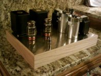
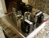
All in all, so far, I am very pleased with the finish. The chassis really turned out quite beautiful. It looks so much better in person. The Canary wood grain is deep and 3D in appearance. I haven't put it on a scale yet but I bet it weighs in at about 50lbs or more!
I am also in the process of hand carving a knob for the volume control out of madera and zebrawood. I will get some final pics by tomorrow (sans the knob, that will take a couple more days).
I will burn it in for a couple of weeks and tweak it a little then it will go up for sale on Audiogon, proceeds to fund my next project, the 300B MK1 mentioned earlier on this thread.
Dear All,
I am also going to assemble this ampli soon. I have a few questions:
1) How come this schematic is so popular, while the one from Jean Hiraga is not ?
2) I see that people use various transformers, with an impedance from 2.5k to 5k. How should I make a choice on that ? (Actually this aspect is not clear to me in general)
3) I saw that the design of the power supply is kind of standard, and I found some improved version with the 10H choke splitted in two, for better common mode rejection. What do you think about ? What about a bleeder resistor ? (470k or so)
4) I also saw that in some schematics the HV+ is connected to the center tap of the 5V secondary (that I do not have). Is it ok if I use one of the 5V AC?
5) In the Hiraga design, I notice that he always put a small capacitor in parallel with a bigger one. What is the effect of this ? in theory they just sum up and adding a 0.47 to 200 will just fall in the tolerance of the big one.
Thank you for helping !!
Davide
Dear All,
I forgot other two questions:
a) Is there any improvement in using DC for the heaters ? From what I understand it could make sense not to have AC signal running in the audio sector at all.
b)If I have a valve with a double triode, and I want to use only half, can I just leave the half I am not using disconnected ?
Thanks,
Davide
Davide,
You have some very excellent questions which I will try to take a stab at. Others, if you find a better explanation, please help me out here
1) I can't tell you and I don't think there are any real psychics here but.....I can say that after just having completed mine.....It sounds awesome and it is very versatile. I imagine this may have a little to do with it. To be sure though, who can say for certain how many of each kind has actually been built.
2) I would stick with the original design of 5K. I went with Edcor CXSE25-8-5k with exceptional results, absolutely no complaint from their products. Me thinks a very good bargain at $80 each. Here: EDCOR - CXSE25-8-5K
3) Again, did it with the basic design above using Edcor 375-0-375 power transformer as follows: 5U4G to 15uF Solen to 100R (brings the B+ down to spec) to a 47uF Solen then to a Westinghouse vintage 10H 77R DCR choke followed by an 80uF ASC oil cap in parallel with a 82uF Solen (162uF total here) then to B+ tap. I also added a 30H 595R Hammond choke and 15uF Solen after the main B+ tap to the transformers. This filters the supply down before the driver tubes even further. I used only one filter for both sides of the driver stage where others have used x2 5H/10uF, one for each side. My voltages are spot on with this arrangement and ripple is essentially absent at the drivers and about 0.008V p-p at the transformers. The issue of common mode rejection is not addressed as well compared to split designs but it sounds perfect like this and is a lot less costly than adding all of that extra iron.
4) I am using a 5V without a CT just fine so, no it is not required. At the Diyaudioprojects.com website the schematic does not use a CT on the 5V.
5) As far as snubbing big electrolytics and even large oil caps, there is a lot to say about this on the Chipamp Gainclone thread, search gainclone and snubberized power supply, you should find plenty to read about there. Although the gainclone is a SS amp, I believe the principal apply everywhere.
And finally, your last 2 questions: I have done exactly both of these with excellent results. Whether or not it makes a huge difference in the noise level on this design, rectifying and filtering the filament supply has always made sense to me and there is much to be said about it elsewhere.
As far as using only 1/2 of the dual triode tube I did it for a variety of reasons. First for the ability to change the circuit to an SRPP 5687 driver stage later. Then I have the x2 tube sockets needed for this ready to go. Second if you are into matching tubes, it is much easier to match sections from 2 separate tubes than it is to match the triodes within a single tube, although they should be very close.
Hope this helps. See my layout at post #107 I think.
Jeff
You have some very excellent questions which I will try to take a stab at. Others, if you find a better explanation, please help me out here
1) How come this schematic is so popular, while the one from Jean Hiraga is not ?
2) I see that people use various transformers, with an impedance from 2.5k to 5k. How should I make a choice on that ? (Actually this aspect is not clear to me in general)
3) I saw that the design of the power supply is kind of standard, and I found some improved version with the 10H choke splitted in two, for better common mode rejection. What do you think about ? What about a bleeder resistor ? (470k or so)
4) I also saw that in some schematics the HV+ is connected to the center tap of the 5V secondary (that I do not have). Is it ok if I use one of the 5V AC?
5) In the Hiraga design, I notice that he always put a small capacitor in parallel with a bigger one. What is the effect of this ? in theory they just sum up and adding a 0.47 to 200 will just fall in the tolerance of the big one.
1) I can't tell you and I don't think there are any real psychics here but.....I can say that after just having completed mine.....It sounds awesome and it is very versatile. I imagine this may have a little to do with it. To be sure though, who can say for certain how many of each kind has actually been built.
2) I would stick with the original design of 5K. I went with Edcor CXSE25-8-5k with exceptional results, absolutely no complaint from their products. Me thinks a very good bargain at $80 each. Here: EDCOR - CXSE25-8-5K
3) Again, did it with the basic design above using Edcor 375-0-375 power transformer as follows: 5U4G to 15uF Solen to 100R (brings the B+ down to spec) to a 47uF Solen then to a Westinghouse vintage 10H 77R DCR choke followed by an 80uF ASC oil cap in parallel with a 82uF Solen (162uF total here) then to B+ tap. I also added a 30H 595R Hammond choke and 15uF Solen after the main B+ tap to the transformers. This filters the supply down before the driver tubes even further. I used only one filter for both sides of the driver stage where others have used x2 5H/10uF, one for each side. My voltages are spot on with this arrangement and ripple is essentially absent at the drivers and about 0.008V p-p at the transformers. The issue of common mode rejection is not addressed as well compared to split designs but it sounds perfect like this and is a lot less costly than adding all of that extra iron.
4) I am using a 5V without a CT just fine so, no it is not required. At the Diyaudioprojects.com website the schematic does not use a CT on the 5V.
5) As far as snubbing big electrolytics and even large oil caps, there is a lot to say about this on the Chipamp Gainclone thread, search gainclone and snubberized power supply, you should find plenty to read about there. Although the gainclone is a SS amp, I believe the principal apply everywhere.
And finally, your last 2 questions: I have done exactly both of these with excellent results. Whether or not it makes a huge difference in the noise level on this design, rectifying and filtering the filament supply has always made sense to me and there is much to be said about it elsewhere.
As far as using only 1/2 of the dual triode tube I did it for a variety of reasons. First for the ability to change the circuit to an SRPP 5687 driver stage later. Then I have the x2 tube sockets needed for this ready to go. Second if you are into matching tubes, it is much easier to match sections from 2 separate tubes than it is to match the triodes within a single tube, although they should be very close.
Hope this helps. See my layout at post #107 I think.
Jeff
Finished!!!!
Well, she is all put together and the results are simply spectacular. I have only listened to it with a pair of KT88 that were manufactured and labeled for McIntosh. Soon I will be changing these out for a pair of Svetlana 6L6-GC tubes.
I did change the grid leak resistor but not to 220K exactly. I had already ordered the 470K PRP resistors when I heard about the change. Fortunately I ordered 2 extra of all of the resistor for the amp. I simply paralleled the extras to the ones on th tag board for a value of 235K.
The sound of this amp has not yet stopped amazing me. I am all smiles when I am in front of it. I haven't had enough time to go through all of my music but there are some of my CD's I can't wait to listen to, especially the ones with vocals highlighted.
Triode is by far the silkiest and sweetest mode but the UL has tons more power and plays load well. The amp does not even clip at full power on triode mode, at least not to my ears. It just seems it wants to be pushed harder and harder....all the way to the top is sweet awesome honeylike sound.
UL is great too, a little more analytical but still warm and smooth. Clipping occurs at about 85% full power. It does not clip hard however and does not punish your curiosity with the control knob above 85%.
I did mine with the pentode option as well. Well, what is there to say really. It is inferior to the other modes but certainly is not bad by any means. It blows away my K-502 in this mode at about 25% volume. It is good indeed but when compared to the others, I will only be listening to this with some hard rock where power is helpful. About power....tons of it in this mode, I have not seen the ratings for it in pentode and am not sure what the wattage is but I would imagine more than 15 watts. It pushes my speakers way forward in this mode and is a bit more shimmering and bright. Clipping occurs at about 60-65% full power (visually on the knob). It is a bit more punishing when it clips in pentode. Where while in UL you can turn it to 100% and tolerate the distortion quite easily, you cannot do this in pentode. I haven't even tried. I like my speakers too much to abuse them like that.
As a final comment on this amps performance all I can say is....YES! Build it if you haven't. It is simply wonderful and the best money I have spent to date on an amplifier project.
In summary, while I have given this detail in multiple separate entries on this post, I will give the highlights of my build here all toghether.
OPTs - Edcor CXSE25-8-5K
Power transformer - Edcor XPWR134
Chassis - Hand-built with exotic woods including Rosewood, Madera, Canary and Dark Cedar with a 1/8" think aluminum plate for the tubes.
Connections - Vampire RCA and Binding posts.
Volume Control - Alps Blue Velvet 100K
Wiring - Silver on signal path and OFC copper on the power supply. RCA to pot and pot to driver tube is Silver shielded Silver 24ga Teflon coated wire NOS from NASA (yes spaceship wire) which is double shielded with copper mesh grounded to Main earth.
Coupling Caps - Jupiter 0.33uF Foil/Paper/Beeswax caps, original style that melt
Resistors - PRP 1watt throughout except Mills on the power tube cathodes and Xicon on the power supply (100R not in original circuit).
Bypass Caps - Black Gate STD series
Power Filter Caps - Eudya Oil (like ASC) 80uF and Solen 630V (82, 47 15x2)
Chokes - Vintage Westinghouse 10H / 77R and Hammond 30H / 595R
Filament Supply - Rectified and filtered with a 8A bridge rectifier and x2 4700uF 25V. Total filter modules #2, one for each channel (XPWR134 has x2 6.3v 3A secondaries)
Construcion - Single Chassis, symmetrical L/R layout, All point-to-point with Tagboards and eyelet standoffs, IEC filter input, Rocker switch, Blade fuse holder, Ceramic sockets, etc..
Options / Tweaks - Toggle selector for 470R to 560R cathode value on power tube. Rotary selector (non-shorting) for Triode, UL, and Pentode modes. Dual Driver tubes (in place of single tube) that uses 1 tube per channel (1/2). Modified power supply filtering (Described in post immediately preceding this one) Addition of a 1K resistor left unconnected for paralleling the 1K driver cathode resistor (with small jumper) to bring value to 500R for 6JD8 tube use in driver stage.
I think that is everything, at least that I can think of at the moment. More pics to follow shortly (wife has the camera) as well as some scope tracings if I can get my signal gen. working properly.
Again, no complaints at all with this build.......I LOVE IT.
Gonna go now......listen to it some more!
Happy Days to all,
Jeff
Lawton, OK USA
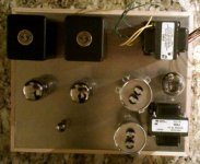
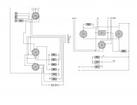
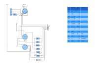
It's always refreshing to hear good answers to good questions! Here is a dry fit layout of the SE KT88 amp. The top and bottom chassis are drilled and the oak base is made. I am going to place the first ASC cap in the CLC PSU inside the cabinet due to space and will determine which value will get the B+ to 400-420VDC. I have 10uF, 15uF, 20uF, 30uF, and 40uF ASC values from which to experiment.
I am trying to get away from another LC filter before the driver plate. Instead of an LC filter, some have mentioned the use of an RC filter (e.g. 100R + 47uF, or 250R + 10uF). I am not sure which will work better which set up will work better?... I want low noise and hum, but not at the expense of dynamics.
I've included a schematic based on the various versions introduced by a Michael Abdulla, Alexg, Porkchop, and Kegger of this SE KT88 Amp. Some have the 1kR before the KT88 and some don't... Again, I am not sure what the difference is, except I've seen more tube circuits with a 1kR grid resistor more often than not. (Oops, forgot to draw gnd).
This is an easy circuit, but the several versions of the schematic make it confusing for the first timer like myself. Here are just a few variables I've encountered on this circuit alone:
1. 330kR plate-to-plate resistor or none
2. (2) 2V LED or 1kR + 100uF cathode bias
3. Driver input filter: LC, RC, or none. 2 filters or 1 shared filter for each channel of 6N1P.
4. 1kR input grid resistor for KT88 or none
5. 1200R output grid resistor for UL or none
6. 100R output grid resistor for triode, UL, and P modes or for only triode mode.
7. 470k or 220k KT88 grid resistor to ground
8. Standby switch or none
9. Input impedence of OTP 2.5kR or 5kR
10. 1M input protection resistor or none
Attachments

Last edited:
Excellent detail and description, Jeff as our threads were minutes apart. My layout doesn't have as many LC networks in the PSU as your build. I hope a CLC design will be enough to suppress and filter noise? I am encouraged to hear about the great sonic results of your build.
That is hilarious, we posted within minutes....probably both pecking away at the same time on our keyboards. I just happened to hit submit first.
Just stuck a pair of 6L6 tubes in.......trying to get a feel for them. They are different, not better, just different.....at least for the 5 mins I have listened to them.
I also tried the 6JD8 tubes without dropping their cathode value to 500R. It works but sounds like it is in a very non-linear portion of the curve. Almost like hitting a reverb switch (though very mild). I can tell the treble is more sharp with them though, can't wait to parallel the 1K to get the value down. I will report on this tomorrow, gotta go to work now (suck).
Jeff
Interesting substitution for the driver. I am curious which will have more of an effect on the sound - changing the driver tube or final tube, as you're substituting both in your circuit? I have only heard (not tested myself) that the 6DJ8 tube may have less bass? But, then again, I am not sure if Sherman had modified the cathode resistor to the range of 500-620R? If changing the resistor does result in a fuller bass, then the effect you described about "reverb" may render the appropriate magic - larger than life, spacious and deep sound stage is a welcome virtue for any tube amp! I could just imagine what an Amperex Bugle Boy 6DJ8 tube will do in this role? However, I do own a matched pair of NOS 1964 Siemens Halske 6922 CCA tubes which I could use (intended for a tube mic which I returned).
Now I am beginning to wonder if I should use the (2) 2V LED cathode bias for the driver tube, because substitutions will not be as easy as flipping a switch. In any case, I've bought parts for either type of substitution. I may just go with the RC cathode bias of paralleling the additional 1kR.
Please, keep us posted with various musical sources and tube rolling....
Earlier in this thread the topic of a 6JD8 was discussed and it was mentioned by someone that the proper bias for the 6JD8 required 470 to 560 on the cathode, not the standard 1K. I questioned the use of this alternate tube b/c the builder of this amp at the diyaudioprojects.com pages suggested he liked the 6JD8 best. The topic was batted around a bit, probably between post 30 and 70 somewhere, I can't be for sure. I actually found both ends of the range to be ok with the 1K resistor in place. I couldn't really put my finger on what it was I was hearing that didn't sound right. I think it was mostly harmonics but not real sure. When I get the scope up and running I will figure it out for sure. Tomorrow I will place the jumpers in place to bring the other 1K into parallel and see how it sounds then. I am loading the amp up in the morning and taking it with me to Dallas where I met a guy on the forums through a friend of a friend online. we have not yet met in person but he offered that if I brought the amp he would hook it up to his system and test it out. I didn't ask if he had a scope but I bet he does as he has built quite a few more amps than I and sounds very well versed in this stuff. Hopefully he will and then I can get some real data to you. We'll see tomorrow. Until then, As Gofar99 always says:
Good Listening!
Jeff
Good Listening!
Jeff
Glad to see everyone is liking this amp!
I actually just changed my bias on the 6N1P to the two 2v red LED's. I really like the sound of the LED's! I'm pulling around 4.8mA through the driver with the LED's as opposed to 3.3mA with the R/C bias. Now I can also switch in a 6DJ8 to see how I like the sound without changing bias components.
I've posted about this over at the "other" site:
KT88 SE Abdellah (modified by Alex Gendrano) - AudioKarma.org Home Audio Stereo Discussion Forums
Glenn
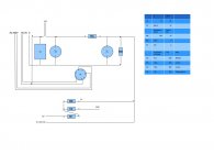
So, I am almost ready to put things together. I spent some time thinking about the layout, and I came with the schematic attached. Please let me know what you think.
I have tried to reduce the paths, and to separate as much as I could different parts.
I will use the James 6123 as OPT.
I had to modify a bit the power supply, as I had 360V and 400V output on my power transformer (PT).
I included the filter for the driver in the power supply sector, so I come with two HV, B+ and B1+.
I plan to build it symmetrically, with the power supply in the center and the ampli on the left and right.
I am not sure how I have to orientate the OPT, as it's not written anywhere how they are built inside.
I try to include the twicks I liked.
Any advice for the choice of the resistors (non inductive, film). I don't know anything about their effect. Which resistors are worth replacing with high quality ones ?
Thanks,
Davide
Attachments
Well, it is a bit dizzying to look at your "schematic", going to and from the parts list and tracing all of the connections here and there. Do you have a more basic, standard looking schematic to post? I see you are planning on using electrolytics for the filter caps on the power supply (unicon). I believe several would agree here that one of the things that make this amp sing is its power supply in it's basic form. Any time you start drastically altering it, expect a different amp than the amplifier that is discussed here. Be sure your voltages in the end are within a pretty tight tolerance to those listed here. My power supply is slightly different but only to the extent I used a series resistor to account for a lower DCR on my choke and a slightly higher output from my transformer. The use of a transformer high significantly higher voltage ratings will change the amplifier "significantly" Some would consider the power supply the "Heart and Soul" of an amplifier and to change it much is to change the entire circuit "much".
Another highly recommended design is the use of ASC (or polypropolene) Motor run caps. I have heard of this amp performing less well with the use of all electrolytics for the filtering. I used both motor run oil caps and Solen poly caps in mine.
I have not seen any modeling of this amp with 0.22uF coupling caps either, I believe the design calls for 0.33uf. Though I am having a hard time following your schematic.
As far as resistors I really think price for performance it is tough to beat PRP. There is not a 2W that I am aware of so you have to get creative with paralleling values to get the desired R. I also use all Mills MRA12 for the cathodes on the power tube. It is not important to use non-inductive in the power supply, a standard ceramic box Xicon will do just fine there. I am a metal film fan personally as they are quieter than carbon types. The only "noise" I want residual in my amp is 2nd Harmonic distortion. Some say Carbon comp resistors give a more "warm" sound but I have yet to hear a compelling argument as to why this is thought to be. I have read plenty about "shot" noise and similar thermal noise that is agreeably higher in carbon comp resistors and none of it sounds any good to me in theory. Also, carbon will drift in value more than the metal film variants. As far as using exotic resistor like tantalum types I have not tried these. I believe ultimately getting the layout done well and getting the tolerances correct are way more important than trying to compensate for a poorly laid out design with poor tolerances by using ultra expensive parts.
Are you planning on using a straight 5000R on the power tube cathode? Are you planning on only using the higher power tubes like the KT88? Did you want to use any EL34 or 6L6 tubes too, if so, the paralleling of a 3K with a 560R is a good option.
I have only heard good things about the James 6123 OPT, in fact I just ordered a pair from vt4c.com for $200. I will be building a 2A3 DHT amp with these. I look forward to trying them out to see if they are any better than Edcor.
Good luck with your build!
Jeff
Step by step
Thank you very much for your comments !
I try to modify a bit the pictures to make them more readable.
About the 500 ohm resistor, for the time being I am planning to use only KT88, but I will leave a space for the option, as I understand it has to be switchable. I am having trouble to find 560 value, so I opted for 500.
For the caps in the power supply, I am having trouble to find an alternative to the electrolitic, so I thought to start with the unicon, as replacing them in a second moment should not be difficult.
The design of the power supply is not really very different from the original. As I start with an higher voltage I had to reduce the first capacitor to have 400V out, and I added an additional RC filter to have the possibility to fine tune the voltage. The calculated ripple goes also down of around one order of magnitude with the additional filter.
It's only that I included in the power supply the filter and the anode resistor for the driver.
I used PSU 2 for the calculations, and I have three questions:
1) in PSU 2, you have to put a resistence for the caps, and I saw, also in the examples that most of the paople leave the default value of 2 ohm. Is it a reasonable value ?
2) In my calculation I used 140 mA as load, as I used some measurement values I found in the first post of this discussion (66*2+4*2). I realized that the original design assume something closer to 170 mA, in this case I would not need the RC filter at all. What's your experience ?
3) in the calculation of the power of the RC filter resistor, I used the values at steady state, I got around 5W and I choose a 10W resistor. Now at start-up there is a peak of around 20 W dissipation for very short time, should I dimension my resistor for the peak ?
Last question, I saw that people choose to put 2 led for the cathode of the driver, to have around 3.5 V. Why not to put one 3.5 led ?
Thanks,
Davide
Attachments
Taking back all of the good things I said about VT4C.com!
I have a bit of a rant.....
A while back I suggested to some on this post that this VT4C.com had such great deals on there parts. Especially the aluminum ring/vent plates to dress up the tube sockets.
Well, I offered to some of you to add to my order since I had a fixed cost for s/h of $100 for up to 20kg and was only using 9.6kg. A few of you took me up on this several days ago so I emailed VT4C to add the extra parts to my original order and to re-issue a new invoice.
Well, sorry to say to the few of you who took me up on this order they just couldn't seem to understand this simple request. For the past sever days, 7 to be exact, this has been a complete cluster you-know-what!
They simply could not understand! I mean for God's sake, how effin hard is it to simply add a few more items to my invoice, which I supplied the number to them and a copy of the original?
My request went as follows: " I need to add a few more parts to the invoice you just issued to me, #xyz. Please add the following items: 1, 2, and 3 and send me a new, updated invoice"
This started a lengthy correspondence of complete and utter confusion on their part which finally ended in a response "sorry we just ran out of items X, Y, and Z" X, Y, and Z being the most important part of my order, which they had when I place the original request.
I have lost all faith in these people. I have canceled my order with them in it's entirety. Sorry to all of you who were going to get a free ride on this deal. I cannot with a clear conscience use this vendor now as me thinks they are not too bright and do not deserve my business.
I think it was an understanding of English that was the problem. I believe they only understand enough to identify a part number and quantity to such a degree that they can put an invoice together. Ask them anything else and it is utter confusion.
I guess I should start learning Chinese anyway, seems to how our current government is trillions in debt to them and our current leadership is asking them to fund even trillions more on social welfare entitlements.....they will soon own us anyway.....
Jeff
Redneckville, USA
Hi,
The schematic on page 1 of this thread is what most folks seem to be basing there build on. If you look a couple of posts down, you will see the link to porkchop61 website with an updated version that, as far as I can tell, the only change is the grid leak resistor for the KT88 to 220K. If you could use a similar format for your drawing and include the changes you would like to, or need to make, it may be easier to solicit a reply.
I can not answer your question about the LED cathode bias specifically, however you might want to post the question on the "other" thread as discussed a couple of posts up.
Good luck.
Thank you very much for your comments !
I try to modify a bit the pictures to make them more readable.
About the 500 ohm resistor, ....
.... people choose to put 2 led for the cathode of the driver, to have around 3.5 V. Why not to put one 3.5 led ?
Thanks,
Davide
Front pic hooked up and running
Hi, I took the amp with me to Dallas this week to show it to a couple of friends. Here it is, finally complete and hooked up to my Madisound RB1 kit speakers. These are the Recession Buster series of kits they produced a while back, I think the drivers and crossovers where about $70!!!. The cabs are handmade out of Double thick Baltic Birch ply (1" thick total) and laminated on the front/top/bottom with some 1/4" thick Black Walnut plank. Crossovers were completely modified with Auricap caps and a Jantzen foil inductor on the tweeter. These little speakers really rock but I bet there sensitivity is at best 88dB and probably more like 86dB. Even with this sensitivity....this amp still rocks!
To keep with the wooden chassis theme I fashioned a knob out of a nice wooden cabinet knob from Home Depot's cabinet section. Just drilled the hole a little bigger an snugged it on the shaft.
I have only been able to listen to it the past 2 nights with my iPod as a source. Not as good as my modded Onkyo CDP but still excellent!
The more I listen to this amp the more I love it!
I was at first thinking I would build it and sell it off to raise funds for another project (this is my "therapy" I build 'em and sell 'em, but not as a business or anything like that) but the more I listen to it I am having trouble with the thought of parting with this one. Usually I would sell them for just a little more than what my cost is in them, I don't know about this one though.....
Anybody have an idea of what an amp like this should bring at Audiogon or somewhere like that?
I have never had a problem selling my amps really quick at Audiogon, I think b/c the prices tend to be pretty low. I am thinking that to sell this one though, I wouldn't just give it away like the others, at least just not yet...
The front Pic was taken with the "crystal eye" cam on the top of my laptop. Sorry for the crappy quality. The Pic of the rear was taken a couple of weeks ago and I just found it and thought I would add it to.
Jeff M.
Redneckville, OK
Attachments


Any thought of possibly running a 7581 in this circuit? Would it work???
Other than the 6L6, EL34, 6550, and all of the KTxx tubes, does anybody know of other tube types that should work in this amp?
Other than the 6L6, EL34, 6550, and all of the KTxx tubes, does anybody know of other tube types that should work in this amp?
- Status
- Not open for further replies.
- Home
- Amplifiers
- Tubes / Valves
- stereo SE kt88 build ... abdellah diyaudioprojects design