The schematic is exactly the same that is in the first post. There are changes in the power supply, as I could not get a 375 V transformer (I have 360 and 400, but open circuit I have 389 and 420)
I am not using both the triode in the driver, just one, and I use only one triode. I posted this question some time ago, and it looks like other people did like this. The first triode is just unconnected.
Thanks,
Davide
I am not using both the triode in the driver, just one, and I use only one triode. I posted this question some time ago, and it looks like other people did like this. The first triode is just unconnected.
Thanks,
Davide
Waiting on parts....
Hi,
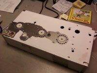
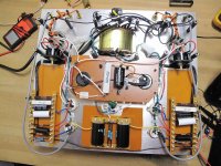
I'm trying my best to join the SE triode party, however I ordered my OPTs from Hong Kong on Nov. 3rd, still waiting. I think they must have fallen off a conveyor belt somewhere and have been swept into oblivion. I've gone about as far as I can with my build. I can't mount the PT & choke because I think it would be too difficult to manipulate the chassis for the OPT cutouts. I have attached a couple of photos of my progress.
Scott
Hi,
I'm trying my best to join the SE triode party, however I ordered my OPTs from Hong Kong on Nov. 3rd, still waiting. I think they must have fallen off a conveyor belt somewhere and have been swept into oblivion. I've gone about as far as I can with my build. I can't mount the PT & choke because I think it would be too difficult to manipulate the chassis for the OPT cutouts. I have attached a couple of photos of my progress.
Scott
Attachments

Hi,
I'm trying my best to join the SE triode party, however I ordered my OPTs from Hong Kong on Nov. 3rd, still waiting. I think they must have fallen off a conveyor belt somewhere and have been swept into oblivion. I've gone about as far as I can with my build. I can't mount the PT & choke because I think it would be too difficult to manipulate the chassis for the OPT cutouts. I have attached a couple of photos of my progress.
Scott
Looks nice Scott.
One thing I would suggest is to anchor the PCB style electros on your tagstrips together just for a bit of mechanical resistance. If you put a blob of silicone sealant between each large electro and its small neighbour, they will share their weight on two sets of leads. I've seen these electros fail due to "wiggling" on their leads.
I would have gone for axial-leaded capacitors, but it comes down to what you have on hand.
I have a question too: What's with all the holes around the tube sockets (or did I miss something in the forum discussion)?
Gary
Hi,
I'm trying my best to join the SE triode party, however I ordered my OPTs from Hong Kong on Nov. 3rd, still waiting. I think they must have fallen off a conveyor belt somewhere and have been swept into oblivion. I've gone about as far as I can with my build. I can't mount the PT & choke because I think it would be too difficult to manipulate the chassis for the OPT cutouts. I have attached a couple of photos of my progress.
Scott
looks nice , there is some problems with honkong post the last months ,i had to wait 5 weeks for my rotary switch wich normally takes 7 days ,i heared the same story from other people at this moment ,so there is a good change they will arrive soon 🙂
grtz ko
I like the idea for the silicone sealant, I'll do that. The caps are Elna Silmic II, only available in radial lead. I wanted to use them as I had read good reviews about these caps.
Theoretically the holes allow for a chimney-effect for cooling when there is a corresponding vent area on the bottom plate. I have seen others do this, and I personally like the way it looks. The overall effect is probably 30% function, 70% aesthetics. One of the members here, jmillerdoc, had posted a parts site that sells plates for this purpose.
seel34, I guess it's not really good news that the HK post is having problems, but it is good to hear that I still might get those OPTs after all. Thanks.
Audio Catalog
I would have gone for axial-leaded capacitors, but it comes down to what you have on hand.
I have a question too: What's with all the holes around the tube sockets (or did I miss something in the forum discussion)?
Gary
:-(
Please give me some hint on how to troubleshoot my amplifier. I am in the dark.
As I said in my previous mail, the amplifier is exactly how is proposed on the first post. The power supply is slightly different, as I had a different power transformer. I put a 39nF/1000V capacitance at the input of the rectifier, then I have a C-LC-RC filter with the following value 4.7uF-10H(81ohm)+100uF-150ohm+100uF. The 100uF are electrolitic, maybe not the best choice, but I don't think this is the problem now. I have 2V p-p ripple on the HT at 100 Hz.
The voltage I get as B+ is too high (460 V) the current drain from the power supply is too low 49mA, and the cathode voltage of the KT88 is too low.
On the output I get 140mV of hum.
At this stage what worries me is not the hum, but the current drained and the cathode voltage.
If there is some test I can do or measurement, let me know.
Thanks,
Davide
Attachments
Hi,
I checked your schematic against the "control copy" and I don't see any errors. I would check and double-check ALL connection points for a possible cold solder joint or faulty ground. I don't think you should have that much ripple on your power supply.
I checked your schematic against the "control copy" and I don't see any errors. I would check and double-check ALL connection points for a possible cold solder joint or faulty ground. I don't think you should have that much ripple on your power supply.
Please give me some hint on how to troubleshoot my amplifier. I am in the dark.
I forgot to tell about the ground: I connected for each ground a wire with a connector. The idea was to have the possibility to play around with the star in the tuning phase. At the moment ALL the connector are tied together with a screw, including the earth of the transformer and from the power plug. The ground is NOT connected to the metal plate.
Thenks, for the advice.
best regards,
Davide
Thenks, for the advice.
best regards,
Davide
hi davide
p=u X I so if your voltage[ u] is higher your[ i ]is ampere will be lower
to get the same p [ watt ] out of your tube ,i don,t see the use of a condensator before the rectifier if i understood you right
for me it would be transformer , rectifier , small elco [10uf] choke
bigger elco , b+ to trafo decoupling, ,then with a resistor to 6n1p, check if this tubes works
in the right way , if these don,t work your b+ on the kt88 also might difference
[sorry engles is not my native langues ]i am trying to translate from dutch
i hope the above ,brings you on a idea that brings you solutions
what the hum concers if you use a ac 6,3v filiament for the tubes look if there is a zero in the middel of the 6,3v output on the trafo,conect this to ground
grtz ko
Last edited:
I have 2V p-p ripple on the HT at 100 Hz.
The voltage I get as B+ is too high (460 V) the current drain from the power supply is too low 49mA, and the cathode voltage of the KT88 is too low.
On the output I get 140mV of hum.
At this stage what worries me is ........
I am worried about it all!
1st the 2v P-P ripple is of the charts, should be in the range of 0.02 or less.
Second, how are you measuring your drain at 49mA, how did you do it?
What was the cathode voltage?
140Mv of hum is really high too....
I am in aggreement with the other writer about checking all of the connections first.
Second, the tube (KT88) could be bad too.
Third, are you getting the proper voltage and current to the filament heaters. If the heaters are not hot enough then you will get less current going through the tube and a higher B+ b/c the the circuit is now stiff. It would also cause the cathode voltage to be low too. I have had this happen to me before, one of the secondaries for my filament supply was faulty and I had niether the voltage or the current, mostly current, to support the filament requirements. You could place a 1R resistor in line series with the filament and check the voltage across it (V=I at 1R). Do the filaments glow brightly, they should.
Certainly if you have somehow measured the powersupply current output at 49mA (normal being about 160mA) and the 6N1P are drawing 10mA (assuming they are) then you have about 20mA going through each KT88, about 1/3 to 1/4 where it should be at idle. Are all your resistor values correct?
I think once you get the power supply fixed your p-p ripple should be in the order of 100x less than what you have.
You said you used a different transformer, what are it's ratings (V & mA)?
There are several possibilities here, but again, I want to know how you measured the current at the output of the power supply. I might have tried something like what I mentioned with the filament, put a 1R resistor just before the take off of the first B+ and measure the voltage across it ( 100mV=100mA if R=1)
To Rotaspec (I think that was the screen name, sorry if I got it wrong),
Check this website if you are interested in a very nice and inexpensive solution to venting at the tube socket. Here: HiFi DIY Site - VT4C/211 Power Triode Look for, I think they are listed as, Aluminum Plates or Tube plates. They are socket mounts made from aluminum or copper with the holes pre-drilled. $6 to $16 depending on aluminum or copper.
I will be interested to see what the proble with the power supply, voltage, current issue is above......
Jeff
Lawton, USA
Troubleshoot
Jeff, thank you for the advices. The power transformer is this one:
PMC-264HGPrimary 95V-100V-105V Secondary 400V-360V-120V-0-360V-400V Dc260mA , 6.3V-4V4A , 6.3V-4V4A , 5V4A , 7.5V-5V3A
With open secondary I get 420 V and 389 V on the 400V and 360 V tap.
It's a little beast, oversized. The only think I do not like is that I measured only 40 ohm between 0 and 400 V. That's why, in the first place I went for the GB as rectifier.
I measured 49 mA of current, as I have an RC filter at the output of the power supply. I put it to tune the voltage with the resistor, as I thought I could have it too high. Now there ia a 150 ohm resistor and 100uF capacitor, and the drop in the resistor is only around 7.5 V.
I will check today the connections. I measured the values of the resistor 20 times to be sure. What I am surprise is that the two channels, that are kind of independent behave in the same way.
I could also try to remake the psu like it should be, 10uF 100uF and see what happen.
Thanks,
Davide
Actually I was really thinking of redoing the psu stage from scratch, sticking to the original project and tuning the voltage with two resistor of the same value before the rectifier. From what I calculated 5 W should be enough. Like this I should have also the advantage that the rectifier sees an higher resistance of the secondary.
I would like to switch to film capacitor. Do you thing it affects in any way if instead of one capacitor with 100uf I put two 47uf (I can add snubber to get over 100uF). Like this I will not have problems with the holes in the plate.
Thanks,
Davide
I would like to switch to film capacitor. Do you thing it affects in any way if instead of one capacitor with 100uf I put two 47uf (I can add snubber to get over 100uF). Like this I will not have problems with the holes in the plate.
Thanks,
Davide
I used all film and my amp is essentially silent. My PSU goes secondaries @375-0-375 to rectifier 5U4G, then to 15uF then 20R then 47uf then 10H then 162uF. After the 162uF I have B1+ to the OPT. Following this I used a 30H 595DCR Hammond choke and another 15uF Solen cap as the stage prior to the Driver tube. My voltages as perfectly at 400 and 390 (it models at 402 and 396 on PSUD2). At the anode of the driver tube after the 47K I have right at 200V. I am different in the first part of the filter as I have CRCLC and your have CLCRC. I am not sure it make a huge difference. I do know the non-use of electrolytics in the power supply in this amp is thought to be of primary importance but, I don't think that is why you are having the wrong voltages and currents. The High B+ is easily explained by the fact you have hardly any current draw. I would imagine if I was only drawing about 50mA off my power supply, my B+ would rise to levels near yours..........in fact during that brief pause I set my total draw at 49mA on my PSUD2 model and I got 468 and 462 at B1+ and B2+ respecively. I will attach the PSUD2 file of my PSU if you want to look at it.
I still think the problem is somehow your bias is off or the filaments are not hot enough or something to where you are not causing the tube to pass through it the proper current (about 80mA each at Idle). Are you sure the cathode resistor on the power tube isn't something like 500K instead of 500???
Are you using the 400+ volt taps on your trafo or the 360V secondaries. I would definitely use the 360v if you are not already....no use in cranking up the voltage only to dissipate all that power with a resistor to get it back down again. The 360-0-360 should be more than enough to get you to 400V after your filter system.
One last consideration. With the high 2v p-p ripple and the very high voltage at the B+ I would consider a shorted choke. That would account for both problems. If it is shorted it will pass the power through unfiltered and un-impeaded cauding both the ripple to be high and the voltage to ge high. It might also account for the low current b/c the 460V B+ might throw the bias point off on the KT88 enough to where, it with the regular spec resistors and such, ends up biasing it at a point with a lower current (I don't have a load line in front of me, it may not in fact cause the current at bias to drop this low, it is a theory that could be solve with a load line).
Check the DCR of the choke and compare it to the rated DCR. If it is much lower, say 5 or 6 instead of 70 or 80, it could (and most probably is) be shorted and a bad choke.
The more I think about this, this is the most plausable theory I can imagine that would give you a p-p of 2V and the high voltage. It would be as if there was no choke at all.
When I change my model on PSUD2 to a choke with 0.001H and 0.1 DCR I end up with a B+ of 416v and a P-P ripple of about 4v. Not as high of voltage but definitely close to the ripple you have.
Let me know what happens, I am still real curious.
Jeff
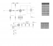
PSUD2 model of my PSU filter
It appears that I cannot share my PSUD2 file without placing it in a compressed .zip extension. I have not tried to send a .psu to another user this way so I don't know for sure if it will work. Give it a try and let me know if you are able to retrieve this file, unzip it, and open it with your PSUD2 program.
To get a free copy of this program go here: PSUD2
Jeff
Attachments
Clearly that wont work!!!
Ok, I tried to download the .zip above and it didn't work so I figured out I could "print" them to an image writer file. I have attached them here this way.
Jeff
Ok, I tried to download the .zip above and it didn't work so I figured out I could "print" them to an image writer file. I have attached them here this way.
Jeff
That didn't work either! The DIYaudio website doesn't suppport .xps files either. Oh well, I tried.
Jeff
Jeff
Jeff,
Thank you so much ! One problem is solved, I followed your hint of checking around the choke, and, for my mistake in the wiring, the LC stage was bypassed. Now the hum is gone.
Unfortunately this did not change much of the other silly behavior. I checked the cathodes, and they drain 1.66 A with only the KT88 and 2.24 A with KT88 + 6N1P. What is a bit high is the voltage, as I read 6.8 V without load and it drops only to 6.7 with the load. I am planning to put the DC regulators anyway, maybe I manage to put one in tonight, and see what happen with the right voltage.
I tried also to eliminate the second RC filter, now I have only CLC(4.7uF - 10H - 200uF)
I also remover the capacitor from the plates of the rectifier, but nothing.
I checked the value of the cathode resistor and are correct. I also have the 3K in parallel, and when I switch it on I get 470 ohm.
I saw that when everything is connected the AC of the heater of the rectifier is only 2 V. I don't know if this is normal. I think I measured it with open circuit, and the value was OK. I have other two 5V secondaries, I'll try to use another one.
What about the resistance of the HT secondary ? I measure only 37 ohm between 0 and 360 V.
By the way, I am using the 360 V tap.
Thanks,
Davide
I tried to refresh all the weldings of one channel, but nothing changed
By the way, I forgot to tell another strange thing. While the plate of the KT88 stays at 460 V, the plate of the driver goes down to 130 V, while it should be 200 V. Like one drawn too much current and the other one too less.
I left pins 1 , 2 , 3 of the driver not connected. Can this create any problem ?
Thanks,
D.
I left pins 1 , 2 , 3 of the driver not connected. Can this create any problem ?
Thanks,
D.
- Status
- Not open for further replies.
- Home
- Amplifiers
- Tubes / Valves
- stereo SE kt88 build ... abdellah diyaudioprojects design