👍I assumed common mode noise for the 1.6 pA/sqrt(Hz) case, maybe that could explain the difference in the third digit.
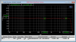
Could you tell what Cart you were using to get a more complete picture.The pre-amp has a very drooping frequency response with little high frequency response.
And what was the length and type of the interconnect that you used, because you will need much more capacity as the shown 10pF to prevent a “drooping frequency response”
Hans
I have some measurements, stock values per NSM and using the 6.8k buildout resistor:
Gain for both 34.5dB
CCIR-486 Noise (Average Method) Stock values = 137uV; Modified values = 132uV
A- Weighted Noise (RMS) Stock values = 52.2uV; Modified values = 50.2uV
Gain for both 34.5dB
CCIR-486 Noise (Average Method) Stock values = 137uV; Modified values = 132uV
A- Weighted Noise (RMS) Stock values = 52.2uV; Modified values = 50.2uV
Attachments

At what source impedance? I guess a fairly realistic one, because the values are not unrealistically low.
52.2 uV A-weighted at the output is equivalent to 983.26 nV RIAA- and A-weighted at the input. Given the noise bandwidth of 3220.23 Hz for RIAA- and A-weighting, that's a weighted average of 17.327 nV/sqrt(Hz).
For RIAA- and A-weigthing, one can calculate with the source impedance at 3850.8 Hz. If all the noise were due to the 1.6 pA/sqrt(Hz) from the op-amp and the 0.5689 pA/sqrt(Hz) from the 47 kohm, you would need an impedance of 10.167 kohm at 3850.8 Hz, so an inductance a little under 420.2 mH.
However, there is of course noise voltage from the op-amp and the breakout resistor and thermal noise of the real part of the source impedance itself, so I guess something in the 300 mH to 400 mH range.
Last edited:
I used an AT VM95SP cartridge across the 47k load resistor -- DCR is 485 Ohms, Inductance 550mH. It's a mono cartridge for 78's
There are two parameters not specified in your measurement, making it hard to compare these numbers with results from LTSpice sims.I have some measurements, stock values per NSM and using the 6.8k buildout resistor:
Gain for both 34.5dB
CCIR-486 Noise (Average Method) Stock values = 137uV; Modified values = 132uV
A- Weighted Noise (RMS) Stock values = 52.2uV; Modified values = 50.2uV
One parameter is the input capacity. When varying a 150pF +/- 50pF, the A-weighted noise will vary +/- 0.3dB.
The second parameter is the BW, which has an obvious substantial contribution.
When simulating with a 485R + 550mH AT VM95SP Cart, gain @1Khz for the NS circuit diagram is 34.64 dB and with the alternative Riaa circuit 34.57 dB.
Using a 150pF total input capacitance and a BW from 20Hz to 20Khz, A weighted noise becomes 68.68 uV-A for NS and 66.93 uV-A for your version.
When dividing these two noise figures by their resp gain being 53.95 (=34.64dB) and 53.52 (=34.57dB), the situation becomes:
EIN A-weighted NS =68.68/53.95 = 1.27 uV and for the alternative version 66.93/53.52 = 1.25 uV.
For the AT VM95SP, output is specified as 2.7mV at 1Khz@5cm/sec.
This results in a S/N resp. of 66.5 dB-A and 66.7 dB-A, an almost insignificant difference of 0.2dB on a relatively low S/N.
Using a OPA2210 would be a far greater improvement in S/N.
Hans
Yes, and with this cartridge inductance, any dual (MOS-) FET op-amp with less than 5 nV/sqrt(Hz) at 1 kHz should slightly outperform the OPA2210.
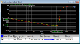
The point of the chart with the THD+N% on the vertical axis, and input voltage on the horizontal was simply to demonstrate that the lower value buildout resistor (R1 in Lipshitz) was less noisy. The lines are parallel while downward sloping, the difference is noise.
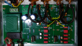
Many thanks for the excellent informative replies from everyone. It's been been very interesting and educative. I started to remove components today to see if there was a large component error. Hooray!...I found the guilty component. I guess it was fairly obvious if I had known the capacitor value code written on it but now I can see it does tally up with the measurement I made on them. They are both 100nF instead of just 470pF (0.47nF)! This brought the total value of the filter up to 126.7nF instead of the 27.2nF as shown on the schematic filter C1 down to ground.. No wonder the pre-amp sounding extremely dull. I've written to the Greek Ebay seller but no response. I'm thinking of using a polystyrene caps in this position to trim up the combined value. Thanks again all.
Attachments

Glad you found the cause.Many thanks for the excellent informative replies from everyone. It's been been very interesting and educative. I started to remove components today to see if there was a large component error. Hooray!...I found the guilty component. I guess it was fairly obvious if I had known the capacitor value code written on it but now I can see it does tally up with the measurement I made on them. They are both 100nF instead of just 470pF (0.47nF)! This brought the total value of the filter up to 126.7nF instead of the 27.2nF as shown on the schematic filter C1 down to ground.. No wonder the pre-amp sounding extremely dull. I've written to the Greek Ebay seller but no response. I'm thinking of using a polystyrene caps in this position to trim up the combined value. Thanks again all.
Have fun with listening to your LP's.
Hans

Thank you Hans. I still need to buy the new components and fit them. I have also emailed again the seller to ask for my money to be refunded. I would never have bought this board if I knew the time I would need to spend getting it to work correctly (still to be ascertained) I feel sorry for the many others who might have also bought these boards with a similar problem, but just accepted the terrible dull sound and fooled themselves it just sounded very "smooth" 🙂.Glad you found the cause.
Have fun with listening to your LP's.
Hans
Last edited:
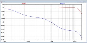
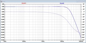
Would you be kind enough to show what a 10% error like 550pf would cause? This would be illuminating.Just for the record, this is what you get when replacing 500pF by 100nF.
Red with the correct 500pF, blue with 100nF instead (both with 150pF input cap).
Hans
Hi, could you possibly measure the cart? My AT-VM95 is 419mh/489ohm, so quite a bit off the 550mh spec. I have a few more AT carts, and none is on spec, oddly. Some are close-ish, some not so close at all. My meter is cheap, but seem to be right on known value resistors and caps. I have few inductors to verify with, but the one I have concur with the measurement from a different meter. I see spec is 550mh@1kHz, I'm not sure if the meter is measuring at 1kHz? How to know?I used an AT VM95SP cartridge across the 47k load resistor -- DCR is 485 Ohms, Inductance 550mH. It's a mono cartridge for 78's
That could explain most of the large discrepancy between measured and simulated.Hi, could you possibly measure the cart? My AT-VM95 is 419mh/489ohm, so quite a bit off the 550mh spec. I have a few more AT carts, and none is on spec, oddly. Some are close-ish, some not so close at all. My meter is cheap, but seem to be right on known value resistors and caps. I have few inductors to verify with, but the one I have concur with the measurement from a different meter. I see spec is 550mh@1kHz, I'm not sure if the meter is measuring at 1kHz? How to know?
With a lower inductance value, a lower input cap has to be used, ca 100pF, also helping to reducing the S/N-A
Hans
Last edited:
With the 419mH/489R and 100pF input cap, the red line shows the FR with 500pF and the blue line 550pF.Would you be kind enough to show what a 10% error like 550pf would cause? This would be illuminating.
As expected, since on the total capacity of 27.2nF it only means a difference of 0.2 %, effect is almost nihil.
Hans
Attachments
That would be a lot closer to the calculation/estimation of post #84.Hi, could you possibly measure the cart? My AT-VM95 is 419mh/489ohm, so quite a bit off the 550mh spec. I have a few more AT carts, and none is on spec, oddly. Some are close-ish, some not so close at all.
Marcel,That would be a lot closer to the calculation/estimation of post #84.
Your calculation was quite accurate.
To get the 52.2uV-A that Jackinnj's measurement showed for the standard NS version, I have to set the coil induction in LTSpice to 401mH.
Hans
- Home
- Source & Line
- Analogue Source
- Spot the mistake on this RIAA pre amp