Thanks very much Hans. The frequency response shown is exactly how I audibly perceive the sound. It was obvious right from the start something was very wrong. What software did you use to create this curve please?...It does not seem to be LT Spice...then again I have not yet managed to use it confidently. Thanks againJust for the record, this is what you get when replacing 500pF by 100nF.
Red with the correct 500pF, blue with 100nF instead (both with 150pF input cap).
Hans
As a precaution, I would try to avoid clipping in the first stage. Things like scratches on vinyl can generate somewhat larger input than normal, so yes, I would only increase gain after the RIAA compensation.
(Sadly one or two of my vinyls have picked up a scratch ... after several decades though.)
(Sadly one or two of my vinyls have picked up a scratch ... after several decades though.)

Inspiring. Marcel, your post #84 made me disassemble my Dual sled to measure the cart, the 550mh seemed high for me too (intuitively, no maths involved). I may have to Buy Better Test Equipment 🙂.Marcel,
Your calculation was quite accurate.
To get the 52.2uV-A that Jackinnj's measurement showed for the standard NS version, I have to set the coil induction in LTSpice to 401mH.
Hans
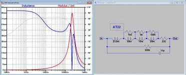
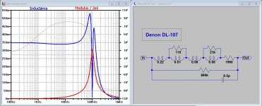
Better test equipment is always nice to have, but be aware that a MM Cart is more than just a Resistor and a Coil.Inspiring. Marcel, your post #84 made me disassemble my Dual sled to measure the cart, the 550mh seemed high for me too (intuitively, no maths involved). I may have to Buy Better Test Equipment 🙂.
See examples below showing the replacement diagrams for two different carts.
As you can see, measured inductance will be highly dependent on frequency.
Hans
Attachments
Last edited:
What equation do you use for the inductance? I would expect it to go negative after self-resonance.
Of course, It does go negative, but displaying the absolute value keeps the vertical axis as detailed as possible. That’s why many VNA’s display it this way.What equation do you use for the inductance? I would expect it to go negative after self-resonance.
Hans
Yes, I wondered about the @1khz spec. Thanks for explaining 🙂. I am very much beginner. Funny, I have both carts in your examples in the house. The omega coiled AT22 measures 67/215, and its identical siblings AT24 is 67/238 and Signet TK9/10 are 67/238 and 73/240 (spec for all is 85mh/240R). The silver wire coiled TK100 measure 67mh/177ohm. So I'm not sure if AT dropped inductance on purpose, or my meter is wrong. It's this one https://www.ebay.com/itm/222235430386 .Better test equipment is always nice to have, but be aware that a MM Cart is more than just a Resistor and a Coil.
See examples below showing the replacement diagrams for two different carts.
As you can see, measured inductance will be highly dependent on frequency.
Hans
The Denon I haven't measured, - yet. It's packed to travel, but I suppose I could unpack it since it seems to be in no hurry. I have some of it's siblings too, the DL-109 and the DL-202 (which has been restored/modified and measures 20mH/100ohm on my meter).
I really miss is a good vinyl source to measure actual FR too, so suggestions are welcome 🙂.
Of course, It does go negative, but displaying the absolute value keeps the vertical axis as detailed as possible. That’s why many VNA’s display it this way.
Hans
So you took abs(Im(Z)/(2 pi f))? It's obviously simulated, so I don't understand what vector network analysers have to do with it.
Several curves are measured with a VNA.So you took abs(Im(Z)/(2 pi f))? It's obviously simulated, so I don't understand what vector network analysers have to do with it.
In LTSpice while inserting components and adjusting their values, I continue until I get exactly the same curves as recorded with the VNA.
That’s how the replacement diagrams came to life.
Hans
Inspiring. Marcel, your post #84 made me disassemble my Dual sled to measure the cart, the 550mh seemed high for me too (intuitively, no maths involved). I may have to Buy Better Test Equipment 🙂.
Regarding the approximations in post #84, when I wanted to design my first moving-magnet phono preamplifier in the 1990's, I had a problem: I had learned how to noise-optimize amplifiers for a given source impedance, and I knew that a reasonable estimate of the source impedance would do, but the impedance of a 600 ohm, 500 mH cartridge varied almost from 600 ohm to 63 kohm from 20 Hz to 20 kHz. What impedance did I have to optimize the amplifier for?
I did some calculations that resulted in a very simple rule of thumb: the magnitude of the cartridge impedance at 3852 Hz. (That was using the IEC modified RIAA curve and A-weighting, it's 3850.8 Hz with pure RIAA and A-weighting, but such small differences are of no practical importance anyway. In the mean time, IEC modified RIAA has been withdrawn.) I made no attempt to publish my calculations, because I thought no-one would be interested in phono amplifiers anymore in the 1990's. Was I wrong about that...
When I realized my mistake, I wrote an article and sent it to Electronics World. It got published in the October 2003 issue, see pages 38...43 of https://worldradiohistory.com/UK/Wireless-World/00s/Electronics-World-2003-10-S-OCR.pdf One of the sections of the gain switch in Figure 5 is drawn in the wrong position (Electronics World's mistake), and the terms spectral density and power spectral density are mixed up (my mistake). I later wrote a follow-up article for Linear Audio volume 8 that extended the idea to other noise weightings and to "damped mode". That article is still behind a pay wall, albeit not a very high one: https://linearaudio.net/article-detail/2211
My calculations were not very accurate, as they neglected the effect of the load capacitance, iron losses and frequency-dependence of the inductance. Nor did they need to be very accurate, as noise optima are usually rather broad and the only purpose of the calculations was to get reasonably close to the noise optimum.
Last edited:
Sonicles, I was just curious to hear if you made any progress.
Just taking out the misplaced 100nf, still without replacing it by 500pF brings you quite close to the originally aimed frequency response.
And yes, answering your question, I created the curve with LTSpice.
Hans
Just taking out the misplaced 100nf, still without replacing it by 500pF brings you quite close to the originally aimed frequency response.
And yes, answering your question, I created the curve with LTSpice.
Hans
Hello Hans. Thanks for thinking of me. I am pleased to say that yesterday I managed to obtain and fit the new capacitors and resistors (to raise the overall gain to correspond more comparably to a CD input). The changes have fixed the problem, it now sounds extremely good. Obviously with far more treble response, the sound is now excellent with so much clarity and "colour" and transparency. It is superior to the inbuilt phono stage of my Technics SL1500 which is probably a single op-amp with active feedback but even so, sounds pretty good but this passive design sounds better. There is HOWEVER just one problem 🙁 there seems to be a rhythmic, slight popping sound in both channels. As the noise is in sync on both channels, I can only assume maybe its the smoothing capacitors in the power supply but the design feeds each op-amp via a 317 regulator so I was thinking this should remove any noise that is on the DC rails?. ..I will try to track the fault down and report it here once I do. Thanks again for your interest Hans 🙂Sonicles, I was just curious to hear if you made any progress.
Just taking out the misplaced 100nf, still without replacing it by 500pF brings you quite close to the originally aimed frequency response.
And yes, answering your question, I created the curve with LTSpice.
Hans
Are you still using the LM4562 ?Hello Hans. Thanks for thinking of me. I am pleased to say that yesterday I managed to obtain and fit the new capacitors and resistors (to raise the overall gain to correspond more comparably to a CD input). The changes have fixed the problem, it now sounds extremely good. Obviously with far more treble response, the sound is now excellent with so much clarity and "colour" and transparency. It is superior to the inbuilt phono stage of my Technics SL1500 which is probably a single op-amp with active feedback but even so, sounds pretty good but this passive design sounds better. There is HOWEVER just one problem 🙁 there seems to be a rhythmic, slight popping sound in both channels. As the noise is in sync on both channels, I can only assume maybe its the smoothing capacitors in the power supply but the design feeds each op-amp via a 317 regulator so I was thinking this should remove any noise that is on the DC rails?. ..I will try to track the fault down and report it here once I do. Thanks again for your interest Hans 🙂
Some of them have this popping problem so you could try a NE5532 or even better a OPA2210.
Hans
That's is very strange, I wonder why this happens?...Maybe it's some form of instability or maybe just a fault within the manufacture of them...perhaps even a fake Chinese clone?. I would say that yesterday, when I first used it cold, the noise did not seem to be there but after an hour or so it had mostly returned. It would be easy to swap and see if a different op amp makes any difference...I will have to buy them though so will not know for several days....Will report back. Thanks 🙂Are you still using the LM4562 ?
Some of them have this popping problem so you could try a NE5532 or even better a OPA2210.
Hans
Later on in the production they seem to have solved this so called popcorn noise, so you might have very early ones.That's is very strange, I wonder why this happens?...Maybe it's some form of instability or maybe just a fault within the manufacture of them...perhaps even a fake Chinese clone?. I would say that yesterday, when I first used it cold, the noise did not seem to be there but after an hour or so it had mostly returned. It would be easy to swap and see if a different op amp makes any difference...I will have to buy them though so will not know for several days....Will report back. Thanks 🙂
The ones I have don’t have this at all
The other problem with opamps at the moment is that many types have very long lead times, but the 5532 is still readily available and are also very affordable for a comparative test.
Hans
Hardly any difference in price between TI 072 and NJM 5532.
It was about 20 cents difference.
For a small quantity, does not matter, I would use the cheaper 072 because of higher slew rate.
It was about 20 cents difference.
For a small quantity, does not matter, I would use the cheaper 072 because of higher slew rate.
The TL072 having 18nV/rtHz doesn’t seem to be a very attractive alternative, does it ?Hardly any difference in price between TI 072 and NJM 5532.
It was about 20 cents difference.
For a small quantity, does not matter, I would use the cheaper 072 because of higher slew rate.
Hans
- Home
- Source & Line
- Analogue Source
- Spot the mistake on this RIAA pre amp