Hallo Pete, good to see you back !!! Jeff and Thimos too !. My Slewmaster with the KND front end is still keeping me happy !!!😉Oh yeah , one of my ORIGINAL builders !!! Old country perfection. Greeks rule !
👍
8 years ago , only one of my builders/testers made one of these input stages.
He "rolled" many a op-amp into this design. he finally tested an OPAxxx op-amp on it.
200+ V/us square waves and phenomenal sound came out - no magic smoke.
Such a strange design , adapted from some obscure corner of the internet.
Completely bonkers design present not only at obscure corners of Internet, but at diyAudio as well by member @Aridace, employing the same basic design principle: https://www.diyaudio.com/community/threads/musings-on-amp-design-a-thread-split.366099/post-7277844
It can provide distortion at -180 dB levels, which is raving bonkers.
I tested circuit at the breadboard. With help of @Hans Polak it was made stable and proved as a viable design. Posts #1230, #1243
As I have done Here .... (below).This is why we pay attention to positioning of ground traces. Route the feeds with returns. Keep loop area short. Power supply hum and noise is low frequency. Ground planes don't allow control of return paths of these currents. No way to steer them around sensitive parts of the circuit.
I rethought the SERVO grounding. On the spooky , unused op-amp ground does not matter. Positive input of the inverting servo op-amp needs
to reference the speaker ground , since it is the speakers DC that you want to cancel. If you used the Rlift ground , a ground fault would screw up that
reference. BTW - direct "G1" is the ideal reference.
On my sub Spooky , I can nearly get to 1hz , the input cap and the servo Fc attenuates below that.
The "VCCS" servo , as well as having diode limiting - just slightly shifts the Vf of the two red led's. Feed +11.4V into "VCCS" and the amp will be at about
-2V at the output. Kind of overkill for worst case conditions.
I've already had 8 years of success with this servo , the Hellraiser should be the same (same "VCCS").
PS - I even attenuate the possible 90V p-p signal to uV through (1 meg) R5 before routing it back to the input stage and servo.
Don't want that "hot wire" passing across my tender circuitry.
OS
Attachments
Last edited:

C1 through-hole pad is on this board (and both IPS's) . I considered it possible to jump it if you want a SMD only unit.C1, the 4.7 uF MKP from the input filter, where will it physically reside?
If you want that big Audiophile cap , mount it right at the input ... it's as big as the whole LTP/CCS stage.
I glad I looked again last night .... ERRORS.
- redundant (R15/16) rail decoupling caps, made them C11/12 and removed 2 more. C4/7 + C9/10 might seem redundant but two are needed
close to the op-amp supply pins.
-I messed up Q7/8 - 9/10 , now all the SOP-6's are facing the same direction. Most SOP-6 packages have a slightly confusing BEC (216-543) clockwise pinout.
some (10%) are made for differentials , I chose what 90% of available common SOT-6's are.
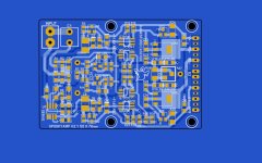
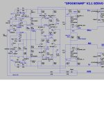
I'm still checking traces from "spooky fixed" . Did creepage , marked all diode/led cathodes , and streamlined traces. Spooky schema is also updated.
OS
Attachments

Last edited:
Good read , I think me and my builder went further and powered a Slewmaster big EF3 with it. Looks like they went through the same OLG/marginCompletely bonkers design present not only at obscure corners of Internet, but at diyAudio as well by member @Aridace, employing the same basic design principle: https://www.diyaudio.com/community/threads/musings-on-amp-design-a-thread-split.366099/post-7277844
It can provide distortion at -180 dB levels, which is raving bonkers.
I tested circuit at the breadboard. With help of @Hans Polak it was made stable and proved as a viable design. Posts #1230, #1243
spread as I did. I used a 3 device fancy current mirrror with the Hawksford , they went "basic".
This is the next IPS , will post the new "fancy" regulated version soon.
- the "EYESEE" , with the big through-hole DIP-8 sitting in the middle of a bunch of matched SMD pairs !!
OS
Spooky is good to go for 50V-60V rails , but most choices for the LTP cascodes in dual packages are limited to 45-65V. Packages
from 80-300V have no standard pinout and can not replace my layout for the LTP cascodes. BC817 plus 846 packages would give
a safe max operating voltage of (11.4 + a derated 55V) for any gender Cascode + LTP.
I DON'T want to have to redesign again or have a IPS that can not take a 100V rail. I am going to make the "Arcwelder V2" , which
will use up to 90V rails.
Hellraiser uses individual cascode SOT-23's , which you can find any range Vceo - 45-300V. No issue with it. Using the duals has it's drawbacks !
So - (below) FMBM5551/5451 @ 160V https://www.mouser.com/datasheet/2/308/1/FMBM5551_D-2313536.pdf will be good for the cascodes.
6pF Cob/ 300mhz/ with lower current gain .... but these are just being used for cascodes - level shift / impedance change duty. It's the high Vceo
I'm after.
I suppose our DIYA requirements for high voltage are not as common for presently manufactured SMD semi's. LOT'S of choices for low voltage ,
which I will retain for the LTP's and audio critical sections of any of my designs. Semi's like our beloved 1381/3503 and 992/1845 are limited
to eBay scammers and old stock. TIME to MOVE ON !!
Attachments
Servo reference ground is G1 (speaker ground) that I can understand. But shouldn't the reference of the feedback path (R31) not be the input signal ground (Glift) ?
That's a good one. Would any DC at the Vlift ground affect the input node ? What would a Vlift DC condition at the NFB node do ?
AND , what effect would a 500mV (DC) difference between the NFB and servo ground reference be ?
OS
AND , what effect would a 500mV (DC) difference between the NFB and servo ground reference be ?
OS
Glift is exclusively for the input signal.
Given normal operation conditions, the difference between G1 and Glift will be low, there is only 2.2 ohm resistance between them.
R31 determines the fraction of the output signal used for NFB. R31 / (R31 + R32)
Given normal operation conditions, the difference between G1 and Glift will be low, there is only 2.2 ohm resistance between them.
R31 determines the fraction of the output signal used for NFB. R31 / (R31 + R32)
Thimios did some testing on different servo ground connections with a Spooky input if I recall correctly. I think he found a substantial improvement in distortion numbers with it connected to the lifted ground.
I thought the whole point of Rlift is to isolate ground loop noise. If the NFB takes G1 as reference, the ground loop noise on Rlift is superposed on the input signal and appears amplified on the output. If instead R31 returns to Glift, only the input signal is amplified and the ground loop noise gain is only 1. Or am I wrong?
Edit : Citation of Cordell's book, Ch.18 : "The negative feedback shunt resistor is returned to the input ground node" (Glift).
Edit : Citation of Cordell's book, Ch.18 : "The negative feedback shunt resistor is returned to the input ground node" (Glift).
Last edited:
But that was with a normal servo. I ported my "VCCS' servo from the CFA amps. Regular servo's suck ! , as they approach F3 they degenerate FBThimios did some testing on different servo ground connections with a Spooky input if I recall correctly. I think he found a substantial improvement in distortion numbers with it connected to the lifted ground.
and make for increased LF THD. I noticed the improvement (VCCS way) on the original "hellraiser" = CFA-X.
OK , say you DID have ground issue with .65V (Rlift diode Vf). I ran ALL simulations -
1. - with servo and NFB at G1 = bad ! Output clipped with 1/2 Vcc DC at output .... ouch !
2. - with servo and NFB at Rlift = better. Output perfect and 1V DC offset . Servo can't compensate for this much DC at input.
3- with servo at G1 (speaker ground) and NFB at Rlift (.65V). Servo tries to compensate , gets down to .2V.
4 - NO servo = amp is a unity gain DC amplifier.
Simulation 3 wins for the least DC and 20hz THD (with a fault).
The Fault might never happen , but "might" still exists.
Spot on !! Unity gain for both noise and a fault.If instead R31 returns to Glift, only the input signal is amplified and the ground loop noise gain is only 1. Or am I wrong?
Another test for my next personal Sub amp ....
1. - no servo and no DC blocking cap. 100mV , most likely the Hfe gender differences - or CCS imbalance. 10ppm @ 30hz -
2.- just a DC blocking cap. 5-20mV depending on frequency. Not bad , I have noticed worse on the real thing. 15ppm @ 30hz -
3. - VCCS servo 30Hz with above option 3 grounding. 200-500uV offset , any frequency. Idle on my present real amp is <50uV.
Glad this was brought to my attention. More "bombproof amp" ! IPS with NO electrolytic's !
OS
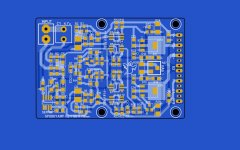
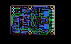
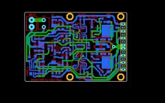
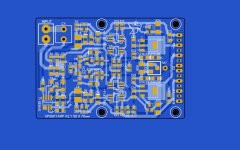
Fixed. Ran R31 through a "quiet" .6V LTP section right back to Rlift ground under the board. G1 and servo FB (R5)
also run through very "quiet" sections (under the board). FMBM5401/5551 's are the new LTP cascodes - good for 100V rails !
Creepage over 1mm in the VAS with soldermask and wide separation of the "tender" low voltage sections from NFB or VAS.
Wow ! I remember fussing over the Wolverine like this.
OS
Attachments
Double $$$#%%hh%it !!! My 2TB files HDD did the click of death !!! I had Badger and Slewmaster backed up on a thumb , luckily.
All my new work is GONE. %%##8^^^ damn.
Lost my TV shows (have blue-ray backup)
Good thing I posted all my artwork here. But not the .LAY's.
It was a Hitachi 2TB HUSxxxx , 4 years old. Not my 8TB helium one (whew!!) Need to buy a new one , maybe a 1TB SSD.
Have a 250GB SSD , will be my new DIYA drive. SSD's seem to be better , my Samsung's are 5 YO.
When I do all this BS work again , I'll post the LAY's and LT files to the first page of this thread. And put it on my thumbdrive.
I am a dummy.
OS
- Home
- Amplifiers
- Solid State
- Spooky and Hellraiser SMD 60W amps (Wolverine compatible IPS)