The op-amp pinouts look like its for a dual op-amp, but the spooky ltspice schematic shows a single type. Is this correct ?

Standard dual servo op-amp , much more common pinout. One op-amp is hooked to G2 ground , the other is setup as a invertingThe op-amp pinouts look like its for a dual op-amp, but the spooky ltspice schematic shows a single type. Is this correct ?
View attachment 1185287
servo. The way this works , any cheap op-amp will work to control the 2 CCS's.
OS
Since you are at the board level ... I will do so at speed. (now).Pete,please if you will find the time,take care for the IPS BOM 🙂
OS
OK , spooky BOM ... both output BOM's -
And Thimios .. if you are using Wolverine boards , you might be at the main OPS BIAS limit for these <4mA IPS's. Wolverine runs at
5+ .... In the simulations , I reduced the resistor in series with the main bias trimmer to 330R.
PS - BOM's will be in the first post in one ZIP file - " BOM.ZIP" , I will put a text file for each PCB in that file.
OS
Pete,take your time.
I will not deliver pcb before end of the next month,i have choose the economy shipping (15-25 days).😞
I will not deliver pcb before end of the next month,i have choose the economy shipping (15-25 days).😞
Last time I ordered from jlcpcb, some weeks ago, they ship to Bari, Italy on 6th of June and the package reached me on 19th. Economy shipping.
8 years ago , only one of my builders/testers made one of these input stages.
He "rolled" many a op-amp into this design. he finally tested an OPAxxx op-amp on it.
200+ V/us square waves and phenomenal sound came out - no magic smoke.
Such a strange design , adapted from some obscure corner of the internet.
I can see many refinements that I can incorporate now.
PS - he was listening to what a TL072 , NE5532 , or any other op-amp sounded like at 100 watts. crazy...
It servo's and plays audio leveraging the source/sink of a common $0 .70 cheap chip....
Hi OS,
Your little spooky amp looks very cool. I like compact SMT front ends and 60W is a nice value for most home audio use.
With regards to your note about using cheap opamps to do high voltage swings as a driver…
I tried out the bootstrapped opamp from 1974 Electronics World article and got a cheap 5534 opamp to swing 70Vpp. Worked quite well.
https://www.diyaudio.com/community/...-easy-peasy-70v-peak-peak-opamp-for-1.314456/
I am also using OPA454 as the driver stage for 0dB gain Class A amps. Here is the LuFo amp that uses this. This one has its own built in DCDC converter for +/-50v on the lower deck of the mezzanine board.
https://www.diyaudio.com/community/threads/lufo-amp-39w-se-class-a-from-28v-rail.372679/
Last edited:
Neato ! Cheepamp power amp hybrid !!
Oh , wow ! Mouser has FJV1845/992's (SOT23) 25c apiece. We can use these for all my designs .... not obsolete.
https://www.mouser.com/datasheet/2/308/1/FJV992_D-2313858.pdf
Will add these to the Spook BOM.
This OPS was built by Evan C. 8 years ago ... runs his big custom 15" bass units to the max with it ! 100% proven bombproof unit !
This new version should work even better (cooler).
SMD BJT's are a bit different than their TH equivalents . Lower Cob , lower Pd , smaller die ?? All my designs are just 1.7-2mA differential
currents = .1W or less and only 11.4V supplies. My only worry is the high voltage VAS. Hence , the low 3.8mA design criteria.
But , we have this neato EF3. I have not noticed much THD degradation <4mA , at 2.8mA ... the Cob of the EF3 pre-drivers up's the THD
to a whopping 11PPM ?
To clarify these amp ratings -
OST mini = either 60 or 100W depending on whether you use 2 or 4 NJWxxxx's - 50V rails.
Arkwelder = 300W/8R or up to 500W/4R with lower rail voltages (SOA dependent). 60-65V rails would be optimum.160V SMD and
TTA/C BJT's would limit safe operation to 70V supplies. SMD VAS BJT choices are slim >160V. I'd rather drive lower Z speakers
with lower rails and better SOA. At least none of my designs depend on obsolete components !
Back to the BOM's.
OS
Oh , wow ! Mouser has FJV1845/992's (SOT23) 25c apiece. We can use these for all my designs .... not obsolete.
https://www.mouser.com/datasheet/2/308/1/FJV992_D-2313858.pdf
Will add these to the Spook BOM.
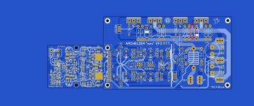
There also is it's VERY big brother - I just finished it ! (below) I'm using it's full (Spooky + Arkwelder) layout to choose the BOM BJT's.Hi OS,
Your little spooky amp looks very cool. I like compact SMT front ends and 60W is a nice value for most home audio use.
This OPS was built by Evan C. 8 years ago ... runs his big custom 15" bass units to the max with it ! 100% proven bombproof unit !
This new version should work even better (cooler).
SMD BJT's are a bit different than their TH equivalents . Lower Cob , lower Pd , smaller die ?? All my designs are just 1.7-2mA differential
currents = .1W or less and only 11.4V supplies. My only worry is the high voltage VAS. Hence , the low 3.8mA design criteria.
But , we have this neato EF3. I have not noticed much THD degradation <4mA , at 2.8mA ... the Cob of the EF3 pre-drivers up's the THD
to a whopping 11PPM ?
To clarify these amp ratings -
OST mini = either 60 or 100W depending on whether you use 2 or 4 NJWxxxx's - 50V rails.
Arkwelder = 300W/8R or up to 500W/4R with lower rail voltages (SOA dependent). 60-65V rails would be optimum.160V SMD and
TTA/C BJT's would limit safe operation to 70V supplies. SMD VAS BJT choices are slim >160V. I'd rather drive lower Z speakers
with lower rails and better SOA. At least none of my designs depend on obsolete components !
Back to the BOM's.
OS
Attachments
Yeah , I was melting copper trying to blow up Sanken MT-200's. Also cooked a 250W sub , on purpose.
Amp smoked the VC , then blew a fuse. Let it cool down , replaced the fuse - worked good again.
OS
Amp smoked the VC , then blew a fuse. Let it cool down , replaced the fuse - worked good again.
OS

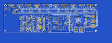
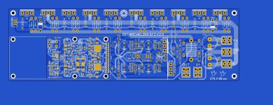
Output stages GALORE ! Arcwelder layout is superior , ported it back to a mini version. Both PCB's have common layout , part #'s ,
tweaked the IPS integration and driver spacing.
Arcwelder -"mini" is 4 output/60-100W , uses TO-220 drivers

tweaked the IPS integration and driver spacing.
Arcwelder -"mini" is 4 output/60-100W , uses TO-220 drivers
Attachments
Thanks JW ! I caught that one late night.
I was thinking of Slewmaster days to finish the big one (below).
Now both are at first post.
A very snotty amp !! Hellraiser would swing full rail to rail in 1/2 uS.
I will add the BOM's right in the package with their corresponding artwork/gerbers.
What is "soldermask offset" in the excellon drill generator ?? Sprint seems to have it set at .3mm ?
OS
Attachments
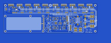
I have been looking at the Wolverine builds .....
I see they use big fat 4mm aluminum heatsinks on the PCB for the drivers, predrivers ... even the VAS !
Don't need that ?? Even the drivers , like on the original HK680 - have no heatsinking.
(below) is standard T651 aluminum ... 2,5mm, spaced the TO-220's and the bigger TO-3p's . Screenprint is 2.5mm
for spacing the heatsink , not the final artwork. On both boards - Q107,103. and Q108 are opposed , heatsink should be sturdy.
Ripple eaters (and predrivers) also need NO heatsinking. Only reason for any heatsinking is to thermally connect Q103 (Vbe 2).
OS
Attachments
I don't use excellion files, not sure what that offset is.
The drivers in the Slewmasters actually ran pretty hot on the sheet metal heat sinks if the rail voltage was high.
The drivers in the Slewmasters actually ran pretty hot on the sheet metal heat sinks if the rail voltage was high.
Uploading Spookyamp_V2.1_package.zip @ jlcpcb.com gives me the following error:
Unable to identify the layers due to the non-standard filename
How do I fix this?
Unable to identify the layers due to the non-standard filename
How do I fix this?
Use standard Gerbers and a .drl file for drilling. You may need to rename the Gerber files to match what they are looking for.
- Home
- Amplifiers
- Solid State
- Spooky and Hellraiser SMD 60W amps (Wolverine compatible IPS)