Can you draw a schematic? I can figure out the supply voltage, it the current supply I might goof up.
Ken
Ken
Think of a CCS. An opamp is ideal here rather than the normal double-diode base bias because of the enormous amount of current the transistor will suck through its base at high currents (wait, who said anything about high currents? I think I'm confused).
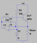
Anyways, if I wanted to test at high currents, I would use something like the circuit attached.
I suppose it all depends on what parts are at hand. It's not totally important, as long as Ic is roughly constant and we can measure the Bf at that point. If you say what parts you have on hand it should be easy to throw something together.
(wait, I just had a thought though. Wouldn't Bf increase anyways if we increased Vce because we would be heating up the die?)
- keantoken
Attachments
50Vce & Ic=10A equates to 500W.(wait, I just had a thought though. Wouldn't Bf increase anyways if we increased Vce because we would be heating up the die?)
How few microseconds (us) can you pass this power and what duty cycle and yet still take measurements without exceeding SOA when Tj<=150degC or Tj<=70degC or Tj<=25degC?
My plan would be to test at a level within the SOA for about 1 second, and see how the voltage used and current generated compares to the hfe at higher levels.
that is precisely where he wants to measure hFE.
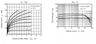
Datasheet shows single shot 10ms pulse with Tj=25degC @ 50Vce
I suspect the graph label Tj should be Tc=25degC.
Single shot pulse of 1second limits the current to 3A @ 50Vce.
Datasheet shows single shot 10ms pulse with Tj=25degC @ 50Vce
I suspect the graph label Tj should be Tc=25degC.
Single shot pulse of 1second limits the current to 3A @ 50Vce.
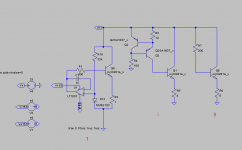
I tried three different layouts. I have a 33v supply, and a 8ohm resistor array rated at about 240watts. Schemes 1 and 2 don't get me very close to the current without lowering the resistor R3(scheme 1) or R5(scheme 2) below the 8 ohms. Scheme 3 simulates fine and resistor R7 isn't disipating too much heat (174mw). Scheme 3 does 3.28A and can be dialed up via R7 reduction. Is Scheme 3 crazy? My supply is robust, but, I don't want to blow up a capacitor or something...
I'm going to look at my DMM and see if it has a peak sample type function. Then I could pulse the switch and dial up the current.
I'm going to look at my DMM and see if it has a peak sample type function. Then I could pulse the switch and dial up the current.
I tried three different layouts. I have a 33v supply, and a 8ohm resistor array rated at about 240watts. Schemes 1 and 2 don't get me very close to the current without lowering the resistor R3(scheme 1) or R5(scheme 2) below the 8 ohms. Scheme 3 simulates fine and resistor R7 isn't disipating too much heat (174mw). Scheme 3 does 3.28A and can be dialed up via R7 reduction. Is Scheme 3 crazy? My supply is robust, but, I don't want to blow up a capacitor or something...
I'm going to look at my DMM and see if it has a peak sample type function. Then I could pulse the switch and dial up the current.
(forgot the schematic)
Attachments

search the LTSpice yahoo group for that error. maybe it's a quirk of 98SE, or the upgrade broke something in the registry.
i've got a question about Early effect...
in a part where there is a large variation in Hfe ranges (2SD2390 for instance). can i expect that the Early voltage remains approximately the same, or does it change a lot from device to device? 2SD2390 has 3 Hfe ranges identified by the suffix (O, P, or Y), O is 5000-15000, P is 10000-20000, and Y is 15000-30000. so should i expect a very similar Early voltage for all 3 beta ranges, or is it likely to be very different?
in a part where there is a large variation in Hfe ranges (2SD2390 for instance). can i expect that the Early voltage remains approximately the same, or does it change a lot from device to device? 2SD2390 has 3 Hfe ranges identified by the suffix (O, P, or Y), O is 5000-15000, P is 10000-20000, and Y is 15000-30000. so should i expect a very similar Early voltage for all 3 beta ranges, or is it likely to be very different?
I recently upgraded from Win98 to Win98SE (very "up-to-date", I know) and now whenever I wish to run LTspice I get this.
So what is that and what impact is that going to have then?
Try right mouse button the icon of the program LTspice properties >> compatibility >> execute in compatibility mode.
(forgot the schematic)
I have only just now found this discussion, and wanted to say, why try at such great currents? The effect of VCE affecting hFE would also be present with much lower currents, without fear of blowing things up or requiring 200W resistor arrays or overheating transistors which will definitely push hFE high and is not what we are trying to measure.
SPICE seems to think this is the case; even at very small currents of a few mA, hFE shoots up with VCE.
I have measured one transistor, MJE15030 I think, and it moved by 1%, not by 50% as SPICE reported.
This weekend I will try to measure more transistors, and see what the effects are. I have a bunch of unused power transistors (200W or thereabouts) and semi-power ones (50-100W) and smaller ones to play with.
not necessarily SPICE itself, but more likely a poor transistor model. very poor, because usually device models tend to be on the "rose colored glasses" side of things.
I have tried at least a dozen models, sources from various places, and they all suffer the ridiculous VCE/hFE change. Now someone posted a datasheet for Toshiba trannies that actually includes the graphs for hFE/VCE and in that graph the changes are ridiculous too, it makes the hFE/Ic graph look irrelevant in comparison.
On the Toshiba graph I attach look at the curve when Ib=15mA - a couple of volts change in Vce and hFE is all over the show. Is this right? My tests (on other transistors) show that it is not. SPICE models seem to want to follow the graph. So, what gives?
On the Toshiba graph I attach look at the curve when Ib=15mA - a couple of volts change in Vce and hFE is all over the show. Is this right? My tests (on other transistors) show that it is not. SPICE models seem to want to follow the graph. So, what gives?
Attachments
why would you think that behaviour of hFE vs Vce at low current and low temperature would be an good indicator for what happens at high currents and high temperatures.IThe effect of VCE affecting hFE would also be present with much lower currents, without fear of blowing things up or requiring 200W resistor arrays or overheating transistors which will definitely push hFE high and is not what we are trying to measure.
SPICE seems to think this is the case; even at very small currents of a few mA, hFE shoots up with VCE.
just go and look at the way the curves of hFE vs Ic cross over each other at high temps and high currents tells you the behaviour has changed from the pattern shown to hold for low temperatures/currents.
I am not examining whether it is an indicator and am not suggesting that the low Ic measurements can be used to extrapolate higher Ics. But to give an analogy testing at 200W and 10A is like saying "I am going to test the brakes on this car by braking from 100mph which is the car's limit" and I am saying "why not test at 10mph first see what happens, cover the basics, then increase the speeds if you think the basics are correct". For if the basics are all wrong then you must not proceed until you fix them.
You drive around with your foot on the brake pedal until the brakes feel like mush and there is smoke and a very bad fishy smell coming out of the wheel arches 🙂
But why do this test if the car does not stop properly at 10mph anyway? Should you not first try to see what is wrong with the brakes or with your expectations ?
But why do this test if the car does not stop properly at 10mph anyway? Should you not first try to see what is wrong with the brakes or with your expectations ?
I have only just now found this discussion, and wanted to say, why try at such great currents? The effect of VCE affecting hFE would also be present with much lower currents, without fear of blowing things up or requiring 200W resistor arrays or overheating transistors which will definitely push hFE high and is not what we are trying to measure.
Akis,
The purpose of my higher voltage/amperage test was an attempt to answer a discussion Andrew and I were having about drivers, pre-drivers and output devices at the extremes of reactive loads on an amp. If you up for even more reading, have a look here: http://www.diyaudio.com/forums/chip-amps/143947-lme49810-std03-parallel-pairs-6.html The meat of the discussion starts at post #55 wherein Andrew throws down the gauntlet 😛
I don't disagree with your wanting to look at the lower levels of voltage and amperage before going onto the big stuff, it just wasn't what I was concerned about.
Regarding testing proceedures, using a switch and a sample and hold multimeter, I was able to switch on and off the power in 1/2second or so pulses. I used 50watts of resistor, which got a bit warm, but not much past about 100deg F. As the current amp I'm working on is a sliding Class A/B amp that operates in Class A up to about 10watts, I did use a pre heated heat sink to better simulate a warm transistor.
Ken
- Home
- Design & Build
- Software Tools
- Spice simulation