Rockwool, Cosywrap or any other trade name for the same product, fibreglass filler is absolutely fine to use.
I agree AllenB. See my writing in #16, where I mention my Sony SS-86E set, filling them with rockwool as well but applying no pressure (maybe compression is a better naming) to the rockwool. Thanks.
From this list I think that 3.3µF is the capacitor series with the tweeter. This capacitor is better to be a film capacitor, not very expensive one but film capacitor. The rest are OK.Galu, I've been looking around at the many options (among them is Mundorf) and ended up with the following replacement capacitors:
2x JANTZEN AUDIO ELECAP Electrolytic Capacitor 100V 22µF 5%
2x JANTZEN AUDIO ELECAP Electrolytic Capacitor 100V 3.3µF 5%
4x JANTZEN AUDIO ELECAP Electrolytic Capacitor 100V 33µF 5%
2x JANTZEN AUDIO ELECAP Electrolytic Capacitor 100V 8.2µF 5%
Looking at the speakers, pretty standard models back in the 90' I guess MKP capacitors is a bit 'out of balance'; looking at their prices also. And as you mention, their size is problematic.
I love the Philips FB-820 speakers. The cabinet is in fact pretty sturdy built, with a 3,5cm thick MDF front baffle and with 2 additional board units halfway inside the cabinet to make it more sturdy. After replacing the cone surrounds with new, rubber versions, the bass became so much better, more 'solid' and 'firm'.
I would describe the FB-820 as sounding 'neutral', with a warmish sound. Have them for over 30 years now.
It's nice you start about this because I thaught about it myself too. But I'm a novice and didn't dare, not knowing if the different voltages of a MKP capacitor matters or not. I read two things about it recently (but with soooo many opinions about it):From this list I think that 3.3µF is the capacitor series with the tweeter. This capacitor is better to be a film capacitor, not very expensive one but film capacitor. The rest are OK.
1 - The mid/higher frequencies benefit especially from better (MKP) capacitors. This is I guess your reason for suggesting a different 3.3uF capacitor.
2 - the higher the voltage, the better. So, I guess a Dayton Audio film/foil 3.3uF capacitor with 250V should be okay then?
The idea is nice, also because of limited space on the crossoverfilter not being an issue anymore as one bigger capacitor should be possible.
Let me first check if the 3.3uF is indeed the one for the tweeter. Thanks for your input.
Personally, I did not feel any noticeable improvement when switching from a 63V capacitor to a 250V one.
From my point of view it is not worth investing in capacitors with snake oil, as I consider these. A 63V capacitor is sufficient for peak powers of 450W/8Ω.
So a 63V-100V capacitor is enough and fits even better in the available space.
From my point of view it is not worth investing in capacitors with snake oil, as I consider these. A 63V capacitor is sufficient for peak powers of 450W/8Ω.
So a 63V-100V capacitor is enough and fits even better in the available space.
I had to look up the term 'snake oil' 🙂Personally, I did not feel any noticeable improvement when switching from a 63V capacitor to a 250V one.
From my point of view it is not worth investing in capacitors with snake oil, as I consider these. A 63V capacitor is sufficient for peak powers of 450W/8Ω.
So a 63V-100V capacitor is enough and fits even better in the available space.
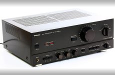
I already ordered the Jantzen capacitors so I'll stick with them. In time I want to take on my vintage amp too (Technics SU-V670) so, with all these many 30 year old capacitors in the audio path already I'm simply happy once they are replaced by brand new ones. I'll leave the true high-end stuff to the others, wether snake-oil or not...I really don't know. Thanks again for your input.
Voltage (within reason) shouldn't make much odds -although I recall that once upon a time, somebody worked up a spreadsheet that indicated Tony Gee's (sighted) cap preferences seemed to fall on a rough line favouring higher voltage ratings. Whether that still holds good I don't know -listening with your eyes and wallet is a trap pretty much anybody can fall into, hence the value of blind tests.
Minor point of interest: lurking on Troels's site is one of his older builds where he ran up a triangle test of the same speaker, using the same crossover design but with one using expensive MKPs, expensive air-core coils and MOX resistors, the second using cheap MKPs, cheap air-core coils and even cheaper wire-wound resistors, and the third using the fancy coils & MOX resistors, but with the caps replaced with bipolar electrolytics. All three were level matched to within 0.5dB. Result? Quoting directly:
Minor point of interest: lurking on Troels's site is one of his older builds where he ran up a triangle test of the same speaker, using the same crossover design but with one using expensive MKPs, expensive air-core coils and MOX resistors, the second using cheap MKPs, cheap air-core coils and even cheaper wire-wound resistors, and the third using the fancy coils & MOX resistors, but with the caps replaced with bipolar electrolytics. All three were level matched to within 0.5dB. Result? Quoting directly:
The result was that I could not for sure determine which session was different from the other two. Simple as that.

And so I move forward being happy with replacing the 30 years old capacitors with the new electrolytic Jantzen versions. I think it does the trick for me being happy with an upgrade and simply enjoying music. And wether that is from my cheap, portable usb plastic 'musicman' (actual device name) which I enjoy listening to when cooking or; turning on my vintage hi-fi set the next morning because I feel like it, in both cases I enjoy the music I hear equally. Thanks Scottmoose for input.Voltage (within reason) shouldn't make much odds -although I recall that once upon a time, somebody worked up a spreadsheet that indicated Tony Gee's (sighted) cap preferences seemed to fall on a rough line favouring higher voltage ratings. Whether that still holds good I don't know -listening with your eyes and wallet is a trap pretty much anybody can fall into, hence the value of blind tests.
Minor point of interest: lurking on Troels's site is one of his older builds where he ran up a triangle test of the same speaker, using the same crossover design but with one using expensive MKPs, expensive air-core coils and MOX resistors, the second using cheap MKPs, cheap air-core coils and even cheaper wire-wound resistors, and the third using the fancy coils & MOX resistors, but with the caps replaced with bipolar electrolytics. All three were level matched to within 0.5dB. Result? Quoting directly: The result was that I could not for sure determine which session was different from the other two. Simple as that.
In time I want to take on my vintage amp too (Technics SU-V670)
It seems you have read about that popular diy pastime, replacing ageing electrolytic capacitors in vintage amplifiers.
Be aware that this poses a greater challenge than recapping a loudspeaker crossover, so be prepared to do your preparatory homework!
The large power supply electrolytics in your quality Japanese amplifier are likely to be within specification, even after 30 years.
The time to take action on those would be when your amplifier begins to show audible signs of distress, such as hum or buzz.
Until such time, an occasional internal inspection to look for any visual signs of component distress may be advisable.
Attachments
Last edited:
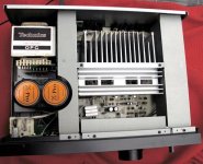
And those twin X-Pro capacitors are pretty special!

"Each X-Pro capacitor is in fact two-in-one. The cans are copper topped and potted into composite materials for less vibrations and even less magnetic leakage."
"Each X-Pro capacitor is in fact two-in-one. The cans are copper topped and potted into composite materials for less vibrations and even less magnetic leakage."
Last edited:
Thanks Galu. I will make sure I dive into the subject a little more before I start the project on my amplifier and making silly mistakes (I do tend to make them 🙂 ). It will for sure be a tougher project but, without pressure; I will take my time. I collected lots of information on my amplifier already (like schematics) and others who made adjustments like recapping (with good results). So far no plans to touch the special X-Pro caps.It seems you have read about that popular diy pastime, replacing ageing electrolytic capacitors in vintage amplifiers.
Be aware that this poses a greater challenge than recapping a loudspeaker crossover, so be prepared to do your preparatory homework!
The large power supply electrolytics in your quality Japanese amplifier are likely to be within specification, even after 30 years.
The time to take action on those would be when your amplifier begins to show audible signs of distress, such as hum or buzz.
Until such time, an occasional internal inspection to look for any visual signs of component distress may be advisable.
Maybe I will first have a look at the capacitors being part of the power supply. Anyway, this is a project for in the future. For now, I'm focussing on my speakers (crossover and damping).
This speaker project already feels like a nice learning curve to me. If it goes well I can slowly move on to the next one. A nice hobby. But thanks again, I will be careful and read into it (probably post the process here as well when the time comes).
Then you'd be following others that have no experience, are not qualified and who just got lucky. There's more going on with an amplifier than meets the eye. I wouldn't attempt this operation without an oscilloscope and the knowledge of why it is necessary.. If you insist, then perhaps you should start a thread in Solid State for support, and you'll know what to expect.and others who made adjustments like recapping (with good results)
There, in the middle, the place to take the negative output for the speakersMaybe I will first have a look at the capacitors being part of the power supply.
The Pic of the caps offers a view on how the connection Is made and that would urge the action of removing the plug and make It 'better'.
A Total or partial disassembly of the chassis and redesign, including a 'vibration suppressor' for the caps, should be ...included...I mean, there's no free lunch!
Also, did I say that crossovers and thereafter speakers work best outside the cabinets?
Last edited:
Okay, maybe I will do something like that (start a new thread). So many different opinions out there...just enjoying all the new knowledge and my hobby.Then you'd be following others that have no experience, are not qualified and who just got lucky. There's more going on with an amplifier than meets the eye. I wouldn't attempt this operation without an oscilloscope and the knowledge of why it is necessary.. If you insist, then perhaps you should start a thread in Solid State for support, and you'll know what to expect.
Wether or not others simply were lucky with their recap I do not want to judge about...I think there are a lot of people out there who now a great deal about the subject...and of course, a lot who don't (the group I belong to), so I will be careful. I dont want to ruin my lovely vintage SU-V670 amp...I want to maintain it properly and keep it in good shape. Thanks.
Oh, by the way; I will first finish the speaker crossover project. If that works out well I will start thinking about the amplifier as being 'a bigger project'.
Last edited:
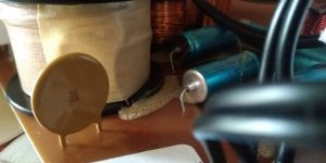
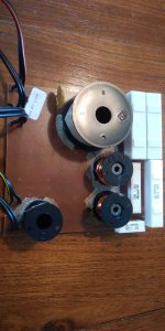
Regarding the PTC resistor on my Philips FB-820 crossover filters: How would you guys by-pass it?
1 - Simply by making a direct connection on the downside of the board and leave the PTC?
2 - Remove the PTC and make a direct connection on the upper-side of the board?
I'm thinking of the first option.
By the way; I want to remove it from the audio chain in the crossover to make the chain 'cleaner'. And I do not need the tweeter to be protected. My Technics SU-V670 never exceeds volume set to halfway so I have no risk whatsoever to blow it. Thanks for any input regarding option 1 or 2.
PS The PTC is the round yellow/brown component sitting in front-left of the picture.
Attachments
Remove the PTC and replace it with a wire link.
Or leave it on the board and short it out with a wire link on the underside of the board.
Either option will work while not disturbing the signal path.
Or leave it on the board and short it out with a wire link on the underside of the board.
Either option will work while not disturbing the signal path.
Last edited:
So today I did some preparatory work while waiting for the new capacitors.
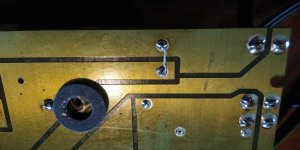
I removed the old capacitors, cleaned the board from glue residues and then bridged the PTC resistor (see two pictures attached).
I choose to leave the PTC attached and simply connect it directly on the underside of the board.
For a novice I'm happy as it all went well and I had no problems.
Now looking forward to placing the new Janzten capacitors. Where I live shipping can easily take some weeks to arrive so I have to be patient 🙂
Once received I'll start the soldering project and post the results here.
Attachments
By the time I place the new capacitors, is the use of certain glue very strict or pretty flexible? The original glue is like a kind of melted glue which has hardened.
When I use new glue, can I use general glue, as used in construction etc. or do I really need a glue specially dedicated to electronics?
My gut feeling is that it can be a flexible choice as long as it becomes pretty hard after drying. I will simply mimic the way the old capacitors were covered with glue. Thanks again for any input here.
- Home
- Loudspeakers
- Multi-Way
- Specs new capacitors for crossover filter