Hello I want to connect the speaker protection circuit with a separate 24V transformer, I can do it as in the drawing. Or where do I connect GND of the PSU of the amplifier. I want to connect a channel of the symmetrical Aleph JX.
Hallo,
ich möchte die Lautsprecherschutzschaltung mit einem separaten 24V Trafo anschließen, kann ich das so machen wie in der Zeichnung. Oder wo schließe ich GND der PSU des Verstärkers an.
Ich möchte einen Kanal des symmetrischen Aleph JX anschließen.
Hallo,
ich möchte die Lautsprecherschutzschaltung mit einem separaten 24V Trafo anschließen, kann ich das so machen wie in der Zeichnung. Oder wo schließe ich GND der PSU des Verstärkers an.
Ich möchte einen Kanal des symmetrischen Aleph JX anschließen.
Attachments
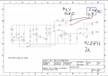
If the transformer is separate then you can just tie the ground of the protection board to the ground of the main amplifier. I would suggest tying it via a low value resistor to eliminate any possible low level interaction, say a 10 ohm 1w carbon or metal film.
HI,If the transformer is separate then you can just tie the ground of the protection board to the ground of the main amplifier. I would suggest tying it via a low value resistor to eliminate any possible low level interaction, say a 10 ohm 1w carbon or metal film.
Doe this schematic has AC loss detection and quick disconnection of speakers?
Not specifically, it relies on the time constant of the reservoir cap and the overall current draw of the circuit including the relays. So it is fairly quick, a 50 milliamp overall draw (300 ohm total relay resistance) might take around 1 to 1.5 seconds to drop out when power is removed.
Board completed ,installed and working. Used a separate 24v transformer from antek. Hear a little more hum in speakers after installation.
If you really need AC detection you can slap an optocoupler with a dropper and a schmitt trigger on it
Hi all,
I have a fully built up protection board that I am going to use in a monoblock amp. I’d like to parallel the 2 speaker channels on the board so that my one output uses both relays. I don’t see why this would cause any issues with the function of the device, but I figured I’d check with people that know more than me first. Thanks!
I would do this by jumpering between SPK1/SPK2 and IN1/IN2
Should be fine. But why? It's better to have higher current through the relays that you'll use. Relays have a tendency to either stick closed or open on lower currents than specified, which is a surprisingly high threshold to reach.Hi all,
I have a fully built up protection board that I am going to use in a monoblock amp. I’d like to parallel the 2 speaker channels on the board so that my one output uses both relays. I don’t see why this would cause any issues with the function of the device, but I figured I’d check with people that know more than me first. Thanks!
I would do this by jumpering between SPK1/SPK2 and IN1/IN2
If you're gonna it anyway, then it should be fine. Your relay contacts are not likely to have tolerances so bad as to cause impedance issues.
Hi there,
I've built the protection board and I seem to having an issue.
Relays are not engaging when power on.
LED1 keeps flashing very fast and never light up steady.
Powering the circuit with 12VAC through a 24V center tapped AC transformer (12v x 2).
Schematics:

PCB

Furthermore the amplifier I use is this one. My question is how should I connect the - (negative) wires of the speaker out(s) to protection board?


I've built the protection board and I seem to having an issue.
Relays are not engaging when power on.
LED1 keeps flashing very fast and never light up steady.
Powering the circuit with 12VAC through a 24V center tapped AC transformer (12v x 2).
Schematics:
PCB
Furthermore the amplifier I use is this one. My question is how should I connect the - (negative) wires of the speaker out(s) to protection board?
Attachments
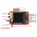
The problem is that the Class D amp does not have speaker outputs that are at zero volts DC. It is a bridge configuration with high DC on both speaker negative and positive.
This means that the DC offset detect of the speaker delay circuit is not compatible with this type of amp I'm afraid. There is no easy fix for that, it would require a totally different type of design.
You can still make use of the delay part though by isolating the offset protection (remove R10).
This means that the DC offset detect of the speaker delay circuit is not compatible with this type of amp I'm afraid. There is no easy fix for that, it would require a totally different type of design.
You can still make use of the delay part though by isolating the offset protection (remove R10).
Since I built this without knowing all that, I will make use of it that way. thank you so much for that.You can still make use of the delay part though by isolating the offset protection (remove R10).
But coming back to the actual issue why I still cannot use this build, any thoughts why the LED1 does not stop blinking and relays do not engaging? I'm doing this test as per the instruction "diyaudio-speakerprotector-build-guide-v1.0.pdf". Only AC power is supplied and amp and speakers are not connected.
Have you tried your test with R10 disconnected?
You should also see the voltage on T3 emitter rise over several seconds as the timing cap charges up.
You should also see the voltage on T3 emitter rise over several seconds as the timing cap charges up.
Folks:
I have an unused diyAudio speaker protection board (V2) which I would like to use in a new project. My understanding is that the circuit was not changed when diyAudio migrated from the V2 to the V3 version of the board (functionality was improved, though), but please let me know if I've gotten that wrong. The board was designed for a 24V supply, but that won't be available in my project. Other than different relays (I have 9 VDC units on hand), can anyone explain to me what changes will be needed when the supplied power is 17 VDC?
Many thanks,
Scott
I don't think any fundamental changes are needed tbh, it should work just fine. The only thing to check is that the relay current (coil resistance) is suitable and not going to draw to much current.
Hello,
Does the protection board get its power from the positive supply of the amplifier? Also my diy amp runs on +- 75 volts is this too high ?
Does the protection board get its power from the positive supply of the amplifier? Also my diy amp runs on +- 75 volts is this too high ?
The board ideally has its own low voltage supply.
It can be powered from rails already present or via a new dedicated supply taken from the AC winding of the existing transformer but there are a few things to consider:
1/ It needs a low voltage supply (around 15 volts DC from memory). So that means adding regulators of some kind before the board.
2/ The supply to the board should have a small time constant meaning the supply falls away quickly on power off.
3/ The board should remain powered even if a fault in the amp occurs that takes any rail fuses to the amp out.
4/ The board has a 'ground' connection to reference it to the audio amp ground. It is important not to create any issues if you power the board from the existing amp supplies.
Thanks for replying I have the perfect small transformer for this. I'm assuming you tie the amplifier ground and protection ground together.The board ideally has its own low voltage supply.
It can be powered from rails already present or via a new dedicated supply taken from the AC winding of the existing transformer but there are a few things to consider:
1/ It needs a low voltage supply (around 15 volts DC from memory). So that means adding regulators of some kind before the board.
2/ The supply to the board should have a small time constant meaning the supply falls away quickly on power off.
3/ The board should remain powered even if a fault in the amp occurs that takes any rail fuses to the amp out.
4/ The board has a 'ground' connection to reference it to the audio amp ground. It is important not to create any issues if you power the board from the existing amp supplies.
- Home
- The diyAudio Store
- Speaker Turn On Delay and DC Protector Board Set (V3)