I have looked through most of this thread and my eyes are glazing over. Every once in a while I see a reference to a build guide, but never a link. Is there one? It doesn't look terribly complicated, but it would be nice to have clear guidance on how to hook it up.
Hey Riki,
From the Store Take a look here... Soft Start & Speaker Turn-On Delay / DC Protector Combo – diyAudio Store
Scroll down there are two sections, one for the Soft Start and one for the Potection circuit.
From the Store Take a look here... Soft Start & Speaker Turn-On Delay / DC Protector Combo – diyAudio Store
Scroll down there are two sections, one for the Soft Start and one for the Potection circuit.
I see a BOM, a schematic, and assembly photos, and the last just takes you to this thread. No build guide linked there, unless I'm missing it.
Riki
https://www.diyaudio.com/media/build-guides/diyaudio-speakerprotector-build-guide-v1.0.pdf
This is the one JoJo did for the original and we are now V3, but if you need hookup guidance you may find what you need in this pdf. If that and assembly phots still leave you unsure, just ask here and someone will help... it's what we do here. 🙂
Last edited:
That would be cool, there are always people out there who are on the beginning end who could use such. I can tell you this from teaching, if one person asks there are many more who have the same questions, but don't ask.
JT
JT
I'm also a teacher and, yes, that rule is pretty well attested. (Plus there are the other people who didn't know they had the same question until it was asked!)
I'm uploading here a revised BOM, as many of the parts on the original are either obsolete or only orderable in multiples of 100.
Saved cart here:
Mouser Electronics
Saved cart here:
Mouser Electronics
Attachments
Good day friends,
I am using a speaker protect unit in an F5 build and it does not want to engage. It gets its power from the AC side of the F5 PSU. Red led just flashes. Yet when I power it from my bench PSU it works 100%
Any advice?
I am using a speaker protect unit in an F5 build and it does not want to engage. It gets its power from the AC side of the F5 PSU. Red led just flashes. Yet when I power it from my bench PSU it works 100%
Any advice?
You have to check the basics first. If it works on a PSU but not in the amp then see what is different. There is only the supply and the trigger inputs.
1/ Confirm the rail voltage across C6 is correct and is not to low.
2/ Try adding a link across R11 as a check against anything from the amp output causing an issue.
3/ Check C6 is the correct value (220uF) and not lower than this.
1/ Confirm the rail voltage across C6 is correct and is not to low.
2/ Try adding a link across R11 as a check against anything from the amp output causing an issue.
3/ Check C6 is the correct value (220uF) and not lower than this.
Good day Mooly
All those parameters are met. But I will check and double-check again.
These modules have been built extremely diligently.
All those parameters are met. But I will check and double-check again.
These modules have been built extremely diligently.
OK 🙂
Don't lose sight of the fact that if it works on a bench PSU then it should also work when powered from the amp as long as the same conditions are met.
If there is to much ripple on the rail (C6) then the LED will keep flashing. Same applies if the supply voltage is to low.
Don't lose sight of the fact that if it works on a bench PSU then it should also work when powered from the amp as long as the same conditions are met.
If there is to much ripple on the rail (C6) then the LED will keep flashing. Same applies if the supply voltage is to low.
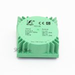
I built a PCB speaker protection, I already have a transformer with two 18V secondaries. 7.5 VA for each rail, I can't connect the outputs in parallel to have only one 18V and 15VA secondary. So I intend to use only one 18V secondary. and 7.5VA. Is it enough to operate the card? 😕
Attachments
Why can you not parallel the windings?
Your picture shows them as separate with no connection between the two. Just be sure to phase them correctly.
Your picture shows them as separate with no connection between the two. Just be sure to phase them correctly.
I built a PCB speaker protection, I already have a transformer with two 18V secondaries. 7.5 VA for each rail, I can't connect the outputs in parallel to have only one 18V and 15VA secondary. So I intend to use only one 18V secondary. and 7.5VA. Is it enough to operate the card? 😕
7.5VA is about 400mA, so current wise there is no issue.
for voltage , 18VAC is enough to operate 5V relays as they are in series.
7.5VA is about 400mA, so current wise there is no issue.
for voltage , 18VAC is enough to operate 5V relays as they are in series.
I have the 12VDC relays (G5LA-14-CF-DC12).
the Volts in output from the transformer without load are 22V.
No-load voltages will be higher. It's in the nature of transformers to saturate their core (if cored that is) and have a higher voltage apparent. If it's a toroidal, you can always add your own winding for small voltages. 😱.
You might also be able to get away with a slightly smaller voltage if you have any other windings at a lower voltage. That I do not know, as I didn't read every post.
18V AC rectified will also work for two relays in series, as the voltage after rectification would be above 24v, and then drop a little because of the voltage drop across the diodes.
(May I mention that that's a very overkill transformer for a protection circuit? That's a nice transformer for a little headphone amp...)
Last edited:
quote " 18V AC rectified will also work for two relays in series, as the voltage after rectification would be above 24v, and then drop a little because of the voltage drop across the diodes."
The pcb has half wave rectifier, so DC volts will be only 16-17VDC with 18VAC input.
The must operate voltage for two of 12 VDC relays is 18V (75% x 12 x 2)
So its a bit risky to operate 2 numbers of series connected 12VDC relays with 18VAC input. The relay coils may not operate reliably.
The pcb has half wave rectifier, so DC volts will be only 16-17VDC with 18VAC input.
The must operate voltage for two of 12 VDC relays is 18V (75% x 12 x 2)
So its a bit risky to operate 2 numbers of series connected 12VDC relays with 18VAC input. The relay coils may not operate reliably.
- Home
- The diyAudio Store
- Speaker Turn On Delay and DC Protector Board Set (V3)