
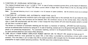
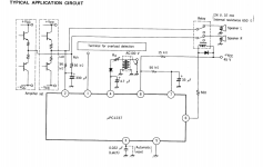
I see the speaker protection circuits, disconnecting speakers as soon as d.c is present in the output and connecting speakers again when d.c stops.
How we can latch the last(fault )condition,no speaker reconnection up to power reset.
How we can latch the last(fault )condition,no speaker reconnection up to power reset.
Last edited:
upc1237 based ssr by bonsai?I see the speaker protection circuits, disconnecting speakers as soon as d.c is present in the output and connecting speakers again when d.c stops.
How we can latch the last(fault )condition,no speaker reconnection up to power reset.
Here are files for you my friend, if you decide to build..Thanks prasi,please give us a Christmas 🎁.
No worries,after Christmas is ok!
Merry Christmas ⛄ to all of you!
Attachments
Any of the following will work fine. 5.08mm x 7.62mm pitch.Prasi:
A follow-up question: what part did you specify for B2?
Regards.
https://www.mouser.in/c/semiconductors/discrete-semiconductors/diodes-rectifiers/bridge-rectifiers/?if - forward current=1 A&mounting style=Through Hole&package / case=DFM~~DIP-4&instock=y&sort=pricing&rp=semiconductors/discrete-semiconductors/diodes-rectifiers/bridge-rectifiers|~Package / Case
Also attaching slightly modified files, where in I have removed the solder mask for speaker traces and also added a pinheader for ground reference.
Attachments
-
BTM COPPER-DIYA SSR PROTECT.pdf18.9 KB · Views: 202
-
 SCH- DIYA SSR PROT.png20.3 KB · Views: 556
 -
speaker protect and startup delay - mod-SSR-TRIAL1_2023-12-25.zip313.2 KB · Views: 226
-
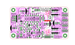 STUFFING GIDE- DIYA SSR PROT.png178 KB · Views: 535
 -
TOP SILK-DIYA SSR PROTECT.pdf41 KB · Views: 164
-
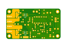 speaker protect and startup delay - mod-SSR-TRIAL1-btm.png86.7 KB · Views: 520
Last edited:
Thanks HRDSTL,
yes, omit Q9, Q10, jumper U$1 pin 1-2, omit R12 (27k) also
R15 of about 560 ohm 0.5W to 1W would do.
yes, omit Q9, Q10, jumper U$1 pin 1-2, omit R12 (27k) also
R15 of about 560 ohm 0.5W to 1W would do.
Any changes to this design? Has it been proven to work?Any of the following will work fine. 5.08mm x 7.62mm pitch.
https://www.mouser.in/c/semiconductors/discrete-semiconductors/diodes-rectifiers/bridge-rectifiers/?if - forward current=1 A&mounting style=Through Hole&package / case=DFM~~DIP-4&instock=y&sort=pricing&rp=semiconductors/discrete-semiconductors/diodes-rectifiers/bridge-rectifiers|~Package / Case
Also attaching slightly modified files, where in I have removed the solder mask for speaker traces and also added a pinheader for ground reference.
thanks very much
Prasi (and others):
Can you please offer some guidance as to how to test for and calculate any adjustments to R15?
Thank you,
Scott
Can you please offer some guidance as to how to test for and calculate any adjustments to R15?
Thank you,
Scott
Any of the following will work fine. 5.08mm x 7.62mm pitch.
https://www.mouser.in/c/semiconductors/discrete-semiconductors/diodes-rectifiers/bridge-rectifiers/?if - forward current=1 A&mounting style=Through Hole&package / case=DFM~~DIP-4&instock=y&sort=pricing&rp=semiconductors/discrete-semiconductors/diodes-rectifiers/bridge-rectifiers|~Package / Case
Also attaching slightly modified files, where in I have removed the solder mask for speaker traces and also added a pinheader for ground reference.
Whats the time on the turn on delay and how would I increase to say 15 secs?
Try increasing C3 to a 68uF or 82uF but they need to be low leakage types. R6 charges the cap and defines the delay but leakage in the cap becomes dominant.
Size R15, for 20-25ma through optocoupler
Monk55 (et. al.):
Yes, I saw that on the pcb but don't understand what it means. I'm looking for actual guidance on how to take the appropriate measurements.
Regards,
Scott
- Home
- The diyAudio Store
- Speaker Turn On Delay and DC Protector Board Set (V3)