Looking at adding the speaker protection board to a Trace Elliot AH150 bass amp. Since this is a mono amp, can I attach the speaker to one side only or do I need to bridge them? Could not find a clear answer on this thread. I also need to get a schematic for this amp to see where I can tap into the power supply.
Thanks, wanted to refer to it for use on a mono amp (Trace Elliot AH150). From what I understand, I can eliminate K2 and R12. I found the schematic for the TE and now need to see where I can tap in for the power for the board.
R12 can be left out for mono but the relay can not directly. You need to replace K1 with one with a suitable coil resistance. That would likely mean a single 12v relay from the same series.
I'm going to say probably OK my only reservation being that genuine original (old) 2N2222's were not a particularly high gain device. Modern parts might well be a quite different to the originals.
Try them, nothing bad will happen.
Try them, nothing bad will happen.
Thanks for the quick response. I was planning on using 12V relays anyway. So from what I understand, I can leave both 12V relays in an eliminate R12. Then hook up the mono speaker to SPK1.
R12 can be omitted or just left floating. Relays or just a single relay if that is all you want depends on the supply voltage you are using.
Hello Forum Members,
I know the topic of supply voltage has been beaten to death so forgive me, but.... I am having trouble finding relays with 6v coils that fit the board. I do have relays with 5v coils that fit however. Could I use a 10VA 10v transformer with them to power the board? I have the following transformer in mind:
https://www.antekinc.com/an-0110-10va-10v-transformer/
I would like a second opinion before I purchase a transformer.
Thank you in advance. Dave M.
Remember that a 10 volt transformer will give closer to 10*1.414 (so around 14 volts DC) after rectification and smoothing. Also at light loading and high mains voltage and the secondary voltage will be a bit higher.
I would fit the relays you have and then measure the voltage across the coil and see where its at. Also many relays have a wide tolerance on supply voltage. The data sheet should tell you exactly what that figure is but it could be as much as a factor 1.1 to as high as around 1.5 so you might not even have an issue. You could always try a small resistor in series with the feed to the rectifier to drop the 'on' voltage if needed.
I would fit the relays you have and then measure the voltage across the coil and see where its at. Also many relays have a wide tolerance on supply voltage. The data sheet should tell you exactly what that figure is but it could be as much as a factor 1.1 to as high as around 1.5 so you might not even have an issue. You could always try a small resistor in series with the feed to the rectifier to drop the 'on' voltage if needed.

Hello,
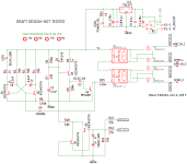
just wondering if the speaker protect board is redesigned with a SS relay, it would find more universal application for any amp.
here is a schema I came up with, which is not tested, but anyone is free to experiment.
if mods find it not appropriate, pl delete the post.
just wondering if the speaker protect board is redesigned with a SS relay, it would find more universal application for any amp.
here is a schema I came up with, which is not tested, but anyone is free to experiment.
if mods find it not appropriate, pl delete the post.
Attachments
Using solid state relays is great idea 🙂 and one I'm all for. You can make small SSR replacements in the same footprint as the originals, something I did with my amp a long time ago. It is definitely the way to go I think.

I've looked at the circuit for the one in this thread and... Arghhh... and there might be a problem. I've got simulations of the original relay version and so it was easy to drop a Photo Voltaic relay in its place. Hmmm... you need to try a real world version I think.
The simulation throws up a problem and that is that the relay drive voltage isn't a 'clean' voltage when a DC offset is present from the amp. What happens is that there are little glitches in the drive voltage and while they do not affect a mechanical relay they do cause an issue with the SSR. There is a lot of ripple on the rail by design of it having a small reservoir cap.
These are the glitches with the mechanical one.

If we expand the trace we see:

Those glitches seem to cause random conduction in the SSR.
Here is the SSR with a simulated offset. The green trace is the speaker voltage and the turquoise the relay drive voltage. The switch on delay is perfect, it when a fault occurs that it behaves oddly. I've tried a few quick things like adding a series Zener to the relay LED but nothing works 🙁

This is the current in the photo relays LED. Those milliamp spikes at the bottom during the simulated offset cause the relay to turn on. The big question is why is that happening and how would a real phot voltaic coupler behave.

I've looked at the circuit for the one in this thread and... Arghhh... and there might be a problem. I've got simulations of the original relay version and so it was easy to drop a Photo Voltaic relay in its place. Hmmm... you need to try a real world version I think.
The simulation throws up a problem and that is that the relay drive voltage isn't a 'clean' voltage when a DC offset is present from the amp. What happens is that there are little glitches in the drive voltage and while they do not affect a mechanical relay they do cause an issue with the SSR. There is a lot of ripple on the rail by design of it having a small reservoir cap.
These are the glitches with the mechanical one.
If we expand the trace we see:
Those glitches seem to cause random conduction in the SSR.
Here is the SSR with a simulated offset. The green trace is the speaker voltage and the turquoise the relay drive voltage. The switch on delay is perfect, it when a fault occurs that it behaves oddly. I've tried a few quick things like adding a series Zener to the relay LED but nothing works 🙁
This is the current in the photo relays LED. Those milliamp spikes at the bottom during the simulated offset cause the relay to turn on. The big question is why is that happening and how would a real phot voltaic coupler behave.
Thanks Mooly, Would a clean supply, like the one i proposed using a regulator for VCC, would that help?
Well I looked and looked and tried lots of stuff and couldn't see the reason why... and then it suddenly hit me. Doh. I had taken the offset sensing from the wrong end of the opto. It was sensing from the speaker and not the amp output. So apologies, my mistake on that one.
So......
We now have this. The 'apparent' glitch at 30 seconds is due to the time constant of the DC sensing, the series 330uF caps and 27k input resistor.

This is the opto LED current. The ripple on the supply doesn't seem to be a problem now.

It is definitely an idea worth pursuing as SSR are (imo) just so much better than mechanical relays.
So......
We now have this. The 'apparent' glitch at 30 seconds is due to the time constant of the DC sensing, the series 330uF caps and 27k input resistor.
This is the opto LED current. The ripple on the supply doesn't seem to be a problem now.
It is definitely an idea worth pursuing as SSR are (imo) just so much better than mechanical relays.
Thanks prasi,please give us a Christmas 🎁.Hello,
just wondering if the speaker protect board is redesigned with a SS relay, it would find more universal application for any amp.
here is a schema I came up with, which is not tested, but anyone is free to experiment.
if mods find it not appropriate, pl delete the post.
No worries,after Christmas is ok!
Merry Christmas ⛄ to all of you!
thanks Mooly for the sim confirmation, still would it be a good idea to use a simple regulator on board? it doesnt take too much space.Well I looked and looked and tried lots of stuff and couldn't see the reason why... and then it suddenly hit me. Doh. I had taken the offset sensing from the wrong end of the opto. It was sensing from the speaker and not the amp output. So apologies, my mistake on that one.
So......
We now have this. The 'apparent' glitch at 30 seconds is due to the time constant of the DC sensing, the series 330uF caps and 27k input resistor.
View attachment 1249711
This is the opto LED current. The ripple on the supply doesn't seem to be a problem now.
View attachment 1249713
It is definitely an idea worth pursuing as SSR are (imo) just so much better than mechanical relays.
- Home
- The diyAudio Store
- Speaker Turn On Delay and DC Protector Board Set (V3)