If you're referring to the way that when they meet an obstacle (or widening radiation space) you'll get a new ripple from that point, with some conditions.
As a wave propagates, any change in the medium in which it is propagating will cause diffraction. So there is even diffraction when the wave meets up with an absorber - some of the diffraction will get absorbed, but some won't.
This is why I've always advised those using felt (primarily for tweeter baffle diffraction) to ensure it's not too close to the tweeter dome itself. I was surprised at how much reflection there is, although it's also frequency dependent. Thick felt can effectively create a "box" around a tweeter at lower frequencies and a partially effective reflective surface at higher frequencies.As a wave propagates, any change in the medium in which it is propagating will cause diffraction. So there is even diffraction when the wave meets up with an absorber - some of the diffraction will get absorbed, but some won't.
Since felt is a porous material, part of the wave passes into and through it and some of it is diffracted/reflected. Due to different ray angle from a dome, the wave exit from the felt should be progressive along the front surface as well. My guess about how felt seems to be so effective at reducing the measurable diffraction effect may be from this distributed mechanism. Thin felt barely works at all, but then little of the wave passes into it. Then there is rapidly diminishing returns from adding thickness. I wish it were possible to visualize the wave with regard to this, since it appears, at least to me, that not all of the reduction is in actual absorption of the wave.
Earl, do you have any insight into this area?
Dave
I don't deal with direct radiating tweeters very much (if at all), but I would be tempted to taper the felt from thin to thick as the taper would offer a less abrupt interface.
I have done similarly to what Dunlavy did, used a stepped approach with success, thin to thick with distance. It's not easy to cleanly cut thicker felt, much less taper it.I don't deal with direct radiating tweeters very much (if at all), but I would be tempted to taper the felt from thin to thick as the taper would offer a less abrupt interface.
My query was more in the line of the mechanism of felt/foam. Is it purely absorptive/reflective or is there an element of time delay? Also, is it partly some additional diffusing effected at the exit in that the wave has gone through something of a circuitous path. What's interesting is that it seems to be effective despite the fact that felt up to a baffle edge is itself a diffracting edge to some degree, especially at lower frequencies where dimensions are still in play.
This may all be somewhat irrelevant, it's more of a curiosity on my part.
Dave
It would appear that "go big and go round" says it all?
I never really got the concept on EnABL'ing a cabinet? I would have to actually understand what it is before dismissing it.
I'd say that EnABL'ing a cabinet is a silly waste of time- it might do something very minor but why not use brute force via felt?
I agree- big and round is the obvious choice. My next project (material gathering phase, now) will use 6" radii on a 36" total baffle width.
Eons ago I would make progressive dampening layers of various materials going from thick to thin. Felt, cotton, lambs wool, fiberglass and two different types of viscoelastic open cell foam and HVAC filter foam (same pore density as Earl uses). Wasn't shy about it either, carving up/shaving layers to control directivity in small rooms. One shape resembled a ejmlc 1000 horn. Ehh, not the same (not a horn) and a tad more duck billed. Friends thought I was wacked with that goofey lookin thing on there. Sounded good, but could never get over the visual. Even chided with making eyes for ports and painting it yellow 😱 😀
I don't deal with direct radiating tweeters very much (if at all), but I would be tempted to taper the felt from thin to thick as the taper would offer a less abrupt interface.
What about diffusing the air-absorber interface to make the transition less abrupt and prone to reflection? Say, by brushing the felt so there's a gradient of hair density or even by going so far as to add fake fur like the dead cat mic covers to the top layer of the felt nearest the tweeter?
^ fluff reduces the reflection (generally) and increases absorption at higher frequencies. Lets say we're working with fiberglass sheeting, on the (relative smooth) face, reflection > refraction > absorption, yet if on edge, reflection < refraction < absorption.
Foam works quite well for a surface treatment over other materials, progressively increasing density with depth. I look at it in a visual way, take a typical board, fairly rough surface and yet if you look at it on edge down the length at an acute angle appears to be smooth like in somewhat mirror smooth. Which in our case would reflect badly.
Earl isn't this in part the design goal for the use of foam in your Summa's?
From acoustic transmission line and closed box theory, the absorbent is known to slow the effective speed of sound as well as converting/absorbing some of it. By this mechanism these enclosures appear larger than their dimensions suggest.My query was more in the line of the mechanism of felt/foam. Is it purely absorptive/reflective or is there an element of time delay?
TBH, I don't think this is the more significant issue here though.
Some questions I have are: When a wave meets an increase in radiation space within the radiative nearfield, how does the contribution of the preceding distribution cause a difference from free space diffraction? and, are energies that are bound to form the outerlying pressure distribution actually tied up, such that they won't contribute to diffraction in the normal way?
Beside what 'normal way' is...which we shouldn't bother as we don't design
regular boxes that are to be packaged and stored 😉
So the beauty of DIY is to make fit a particular design to your room & music tastes; but as we (may) know, most of the acoustic things are well predictable and there are the sub-genres such below Shroeder's frequency etc etc but the mid and treble are the most susceptable to create artifacts...which happen to fall in our ear's most sensitive region, as also brain that makes the relationships between them and extrapolates ( something). So after having defined what has to reach our ears, which is mostly the first emission + some spurious interferences + reverbered sound -we can control those three levels of emission ; what comes to mind is the decay in time, so each level should follow the natural rise, duration and decay of a note.
The interface between free space and any material - be it absorptive or not - will be composed of an absorbed portion and a reflected portion. (Absorption here meaning propagation into the 2nd medium where it may or may not be absorbed - it is absorbed as far as the first medium is concerned.) The greater the difference in the wave impedance of the two media the greater the reflection and less the absorption. The reflected part gives rise to diffraction. Gradually introducing the absorptive medium reduces the reflection - think wedges in an anechoic chamber. "Gradual" means with respect to a wavelength.
I use foam purely for absorption and its density is selected to yield the least reflection with the most absorption. There is actually a fairly narrow range of densities where this is optimum. So you just can't go out and get any-old foam. It needs to be of the right density or it will be too reflective or not very absorptive. The porous nature of the foam does yield a small gradient transition to the wave impedance, but this would only be of sufficient depth to be effective at the higher frequencies. But that is primarily where it is most effective. I find almost no effect of the foam at the lower end of the bandwidth of the waveguide. HOMs are a higher frequency issue however, so the fit is just right.
I use foam purely for absorption and its density is selected to yield the least reflection with the most absorption. There is actually a fairly narrow range of densities where this is optimum. So you just can't go out and get any-old foam. It needs to be of the right density or it will be too reflective or not very absorptive. The porous nature of the foam does yield a small gradient transition to the wave impedance, but this would only be of sufficient depth to be effective at the higher frequencies. But that is primarily where it is most effective. I find almost no effect of the foam at the lower end of the bandwidth of the waveguide. HOMs are a higher frequency issue however, so the fit is just right.
Last edited:
Some years back tested what I had been using for grill foam for the last 35 years or so. Had read info long ago in print (some mag review probably) on the use of diffraction control and directivity and what you are using (and for why) in your designs. Bells went off, because we agreed. Having had the pleasure of auditioning some of yours over the years, so I would say exactly the same, just a different source 🙂 My father designed hvac systems and in the shop all sorts of oddball things considering our vast hobbies. We had this on large rolls 3/8" x 16", 5/8"x18" and 1"x20"
BTW we also built varieasy's and long easy's including the custom made vacuum formed optically perfect canopies. So you can imagine the vast variety of materials and tools that go into prototyping composite aircraft ie the shop wasn't the garage 😉
BTW we also built varieasy's and long easy's including the custom made vacuum formed optically perfect canopies. So you can imagine the vast variety of materials and tools that go into prototyping composite aircraft ie the shop wasn't the garage 😉
I never really got the concept on EnABL'ing a cabinet? I would have to actually understand what it is before dismissing it.
For me even some measurements of the effect would suffice. Unfortunately I haven't seen any yet.
so:
A spherical enclosure would be nice because it has the lowest possible diffraction, but it is very difficult to make.
Do the largest radius that you can reasonably do. I can do 1.5" with no more trouble that 1",so I do that. To go to 2" requires special tooling, so I don't do that.
"Finish the rough radius with hand tools or sander." is exceedingly tedious and time consuming.
OTOH:
It's not easy to cleanly cut thicker felt, much less taper it.
yes, indeed
so:
It would appear that "go big and go round" says it all?
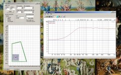
perhaps not, I played some with the Edge and below is an Edge simulation - no sphere, straight sharp edges, no felt, no waveguides but certainly looks interesting
Attachments
Go back to the original thread and/or the second technical thread. You'll find measurements made by John K that show what one would expect, no affect on a baffle. Despite the actual measurements, proponents did the usual, dismissed them with excuses. They don't produce them (though many could I'm sure), it lets them still believe that it works. But please don't bring that debate into this thread. It's mostly dead and should remain that way.For me even some measurements of the effect would suffice. Unfortunately I haven't seen any yet.
You've got effectively a large area square driver (36 single-point drivers). It's not realistic. A round one with diameter equal to that size will likely look good. See what it does with a more realistic driver. Try it with a single tweeter with a realistic density, then do off-axis plots or a small midrange, maybe 130mm. Be sure to do the off-axis, since that's what's important, at least across some listening window.perhaps not, I played some with the Edge and below is an Edge simulation - no sphere, straight sharp edges, no felt, no waveguides but certainly looks interesting
dlr
don't bring that debate into this thread. It's mostly dead and should remain that way.
it was not my intention - I swear 😀
You've got effectively a large area square driver (36 single-point drivers). It's not realistic.
I am thinking of a real 32 mm wide range speaker, Visaton BF32 perhaps, such drivers are pretty close to a point source:
An externally hosted image should be here but it was not working when we last tested it.
a 10x10 square array of a bit larger drivers has been tested:
http://www.diyaudio.com/forums/full-range/164797-200-x-2-drivers-what-do-8.html#post2160121
a 6x6 square array seems feasible
why not?
The diffraction concern is largely moot with that configuration, with the exception of baffle step. The issues with that arrangement aren't applicable to the topic here, in my opinion. If you consider a single one of those in isolation, they are not close to point source. No driver is.a 6x6 square array seems feasible
why not?
Dave
perhaps not, I played some with the Edge and below is an Edge simulation - no sphere, straight sharp edges, no felt, no waveguides but certainly looks interesting
I did a project with a similar shape some years back:
DIY Open Baffle With Widerange Drivers A.K.A. The third ugliest amazing speaker you'll ever see. Article By Jeff Poth
The build was rough as it was done in a transition period (I had only battery powered tools) but the shape was optimized for minimum diffraction, along with liberal use of felt.
Sounded great.
- Status
- Not open for further replies.
- Home
- Loudspeakers
- Multi-Way
- Speaker cabinets and edge diffraction